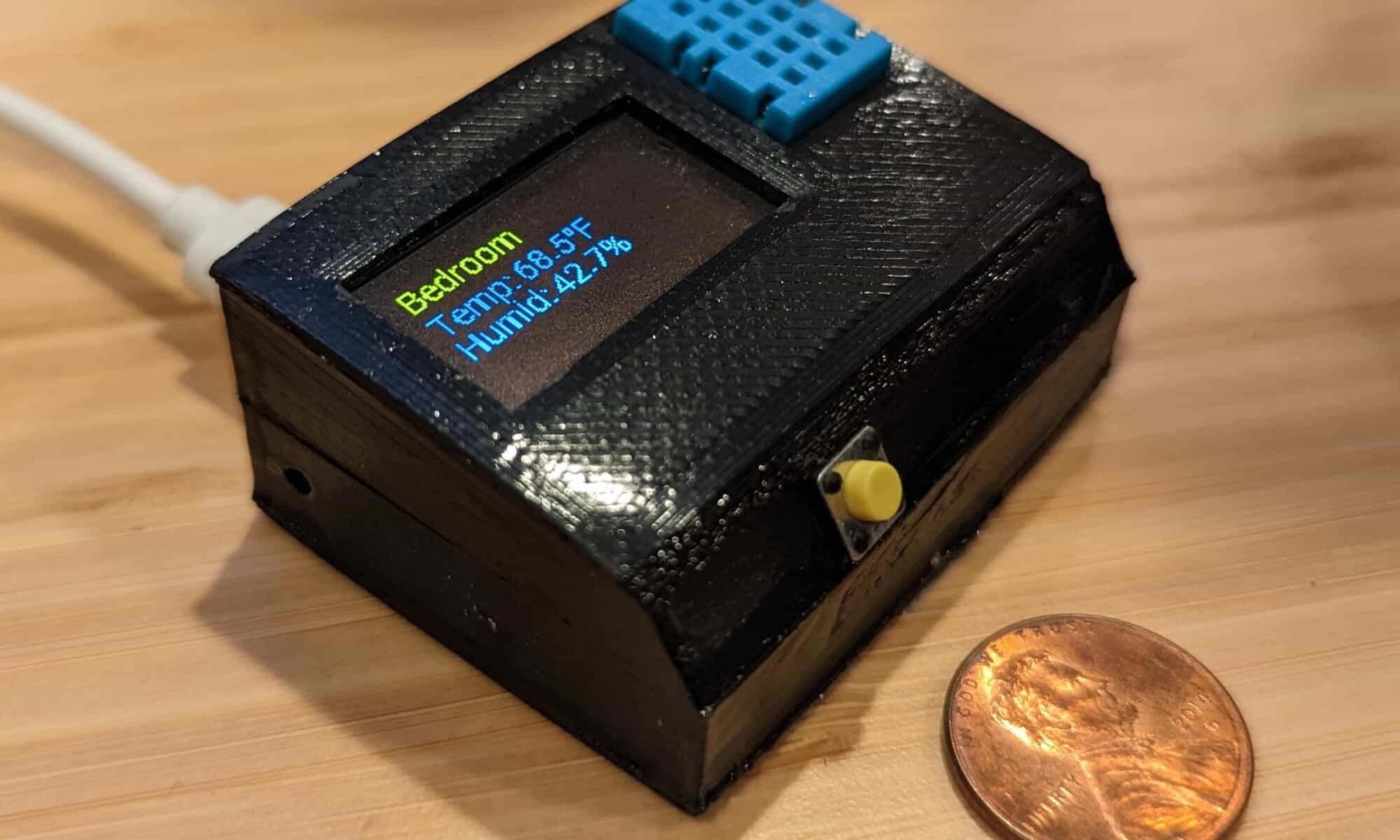
For the 3 people that have been reading my posts, you know my journey from ESP8266 hacking off the shelf smart switches to creating custom devices, most of which I connect to Home Assistant so that smart devices are secure and don’t rely on the existence of any particular vendor. The next step in this journey is using ESPHome to simplify creation of custom software for ESP8266/ESP32. For my first project I created ESPHome Temperature and Humidity with OLED Display.
Why ESPHome?
Why use ESPHome instead of something like Arduino Studio? Simply put, its simple but powerful. As an example, I made custom software for a temperature & humidity reader for my bathroom that was 8 custom lines of code (which wasn’t really code, but configuration). YAML configuration files provide access to a ton of sensors, and if you need to dig in deeper with more complicated functionality, ESPHome provides Lambdas that allow you to break into custom C++ at any time.
One of the other cool things about ESPHome is, while it integrates seamlessly with Home Assistant, the devices are meant to run independently, so if a device is out of range or has no network connection, it still performs its functions.
And I wanted to learn something new, so…
Why This Sensor?
I have a few temperature sensors around the house and I also keep one in the camper van, mostly out of curiosity so I can compare it with the in-house temperatures using graphs on Home Assistant. However, I realized that when I went camping I wanted access to the temperature, but couldn’t do so without being connected at home. The old version of the van thermometer was based on an ESP8266 Garage Door opener (I never shared that posting, so sorry, or you’re welcome) and I didn’t want to update it with a display screen, as I really don’t need that for a garage door (yes, I realize something not being needed usually doesn’t stop me from building it). I decided that I might as well take the opportunity to use ESPHome since it was simple and worked offline.
It’s Time to Build
I won’t go into the details of setting up Home Assistant, but if you are into home automation at all, it is super awesome. Installing the ESPHome add-on gives enables the flashing and managing of ESP8266/ESP32 boards, and they automatically connect to Home Assistant at that point.
For the lazy, ESPHome is generally a few clicks and a little copy pasta. For this project, it’s no different, with the step-by-step details available on my Github project page.
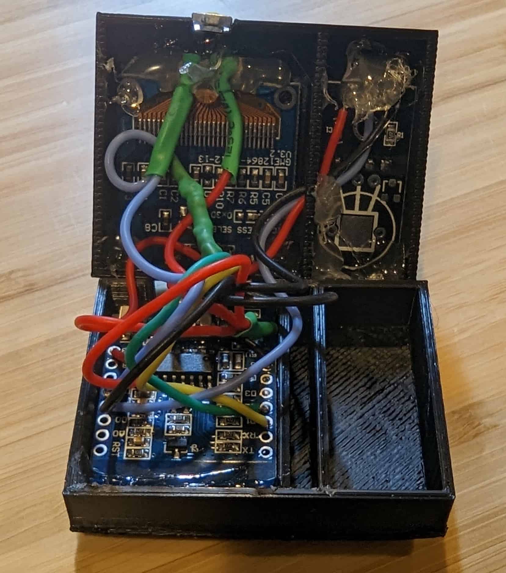
Wiring complete on DHT11 and ESP8266 (ESP-12F) before gluing case together
For the hardware, I used the very tiny ESP-12F, DHT11 sensors, this OLED display, and a few miscellaneous components. All of these fit pretty nicely in the case, although it is a pretty snug fit, so I highly recommend a very thin wire, and this 30 Gauge silicone wire was super great for the job. Exact components, wiring diagram, and the STL files to 3D print the case are on my Github project page.
When assembling, removing the pins from the DHT11 board and soldering the wires directly to the board will allow it to be flush against the case, giving better exposure to the sensor and fitting better. The DHT11 is also separated from the ESP8266 board as I was hoping to create some insulation from any heat from the board impacting the temperature reading (not sure that work). There is a hole between the chambers to thread the wires, and I suggest a bit of hot glue to block air flow once wired.
As you can see in the photo, I used generous dollops of hot glue to hold the components in place… it isn’t pretty, but nobody will ever see it (well, unless you photograph it and blog about it, in which case still, probably nobody will see it). I sealed the case with Zap-A-Gap glue, as I found original Super Glue was way less effective.
Instructions
Plug it in.
Okay, well… it’s a little more than that. The screen will alternate between showing the temperature and humidity in text format and a 24 hour graph that is a bit useless for now since I am not sure how to get the historical values to label the graph. The button will toggle screen saver mode on / off, and the screen saver activates automatically after a short amount of time.
If you want to get a little fancier, I have this sensor in the bathroom and it will turn the vent fan on (via Home Assistant) when the humidity reaches a certain level… it’s useful for anything where you want to control devices based on temperature or humidity, and even more useful if someone might want to see the temperature.
Are you doing home automation with ESPHome? Do you have suggestions or requests? Did you actually read this blog post for some reason? I want to know… please leave a comment, below!
I frequently commute on BART and wanted a convenient way to tell when I should start walking to the train station, ideally something that is always accessible at a glance. A gloomy Saturday morning provided some time to hack together something…
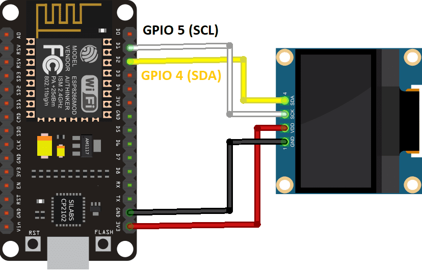
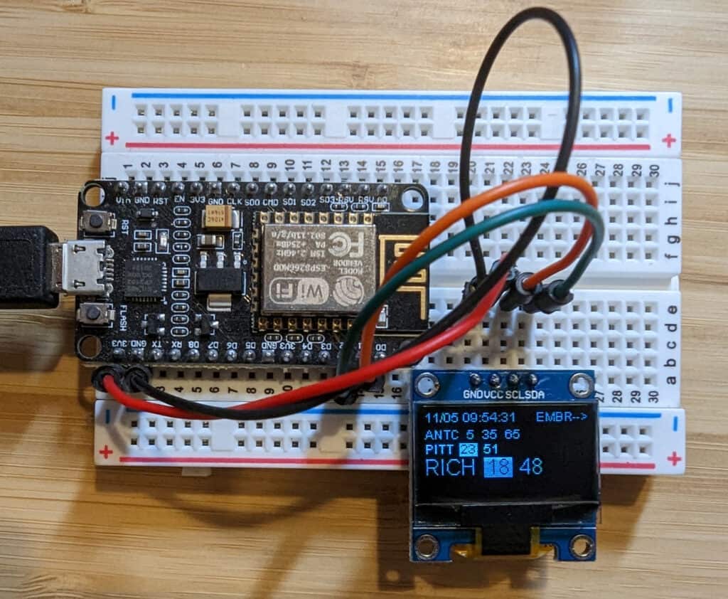
ESP8266 to SSD1306 wiring diagram
I had already purchased a ~1 inch SSD1306 display and had extra ESP8266 boards laying around, so I figured I would start there. Wiring the screen to the board is super simple, just 4 wires (see diagram).
From there is was pretty simple to pull the train real-time data using BART Legacy API. BART also offers modern GTFS Schedules, which is the preferred way to access the data, but from what I could tell, this would make the project significantly more difficult given some of the limitations of the ESP8266. So, I went the lazy route.
Coding was pretty simple, most of the time was spent rearranging the elements on the screen. Well, actually most of the time was spent switching from the original JSON and display libraries I chose as I wasn’t happy with them.
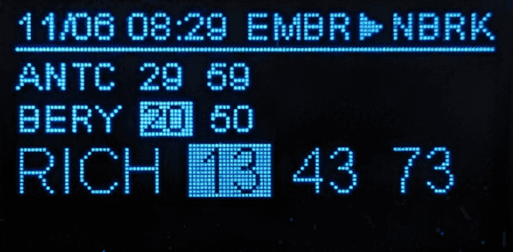
BART-watcher-ESP8266 (early layout)
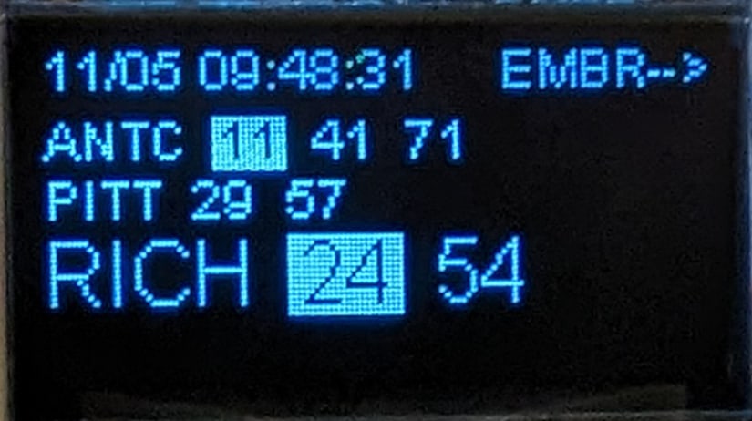
There’s a lot to fit into a 1-inch display, but I got what I needed. The top line shows the date / time the station information was collected, and the departing station. The following lines are trains that are usable for the destination station, with the preferred (direct) lines in large type, and less-preferred (transfer needed) in small type. Finally, if a train is within the sweet spot where it isn’t departing too soon to make it to the station but I also won’t be waiting at the station too long, the departure time is highlighted. Numbers are minutes until departure, “L” means leaving now, and “X” means the trains was cancelled (somewhat frequent these days).
In the example above, these are trains leaving Embarcadero for the North Berkeley station (not shown), Antioch and Pittsburg/Bay Point lines require a transfer, Richmond line is direct.
At some point I would like to use a smaller version of the ESP8266 board and 3D print a case to make it a little nicer sitting on a desk, but then again, there’s almost zero chance I’ll get around to it. If anyone is into 3D printing design and wants to contribute, I’ll give you all of the parts needed.
The code / project details are available on my GitHub page at BART-watcher-ESP8266, feel free to snoop, contribute, or steal whatever is useful to you.
The full build of BART Watcher on ESP8266 and SSD1306 OLED display
Do you have suggestions for features you think would be cool, want to remind me that I waste a lot of time, or maybe you even want one of these things? Please leave a comment, below!
I’ve been incredibly impressed with AI image generation, in how far it has come and how quickly advances are being made. It is one of those things that 5 years ago I would have been pretty confident that it wouldn’t be possible and now there seems to be significant breakthroughs almost weekly. If you don’t know much about AI image generation, hopefully this post will help you understand why it is so impressive and likely to cause huge disruptions in design.
Midjourney AI-generated image, “beautiful woman, frolicking in water, gorgeous blonde woman, beach, detailed eyes”
As a quick background, AI image generation takes a written description and turns it into an image. The AI doesn’t find an image, it creates one based on being trained looking at millions of images and effectively learning patterns that fit the description. The results can be anywhere from photo-realistic to fantasy artwork or classical painting styles… almost anything. There are several projects available for pretty much anyone to try for free, including Midjourney, Stable Diffusion, and DALL-E 2. I am using DiffusionBee that runs from my MacBook, even without a network connection (i.e. it isn’t cheating and pulling images off of the Internet). Oh, and image generation is fast…. from a few seconds to about a minute.
If it isn’t obvious why this is amazing and likely to be massively disruptive, imagine you need a movie poster, blog images, magazine photos, book illustrations, a logo, or anything else that used to require a human to design. The computer is getting pretty good and can generate thousands of options in the time it takes a human to generate one. It can actually be faster to generate a brand new, totally unique image rather that search the web or look through stock photography options. For example, the robot image featured at the top of this posting was generated on Midjourney with about 5 minutes of effort.
As a practical example, recently Sticker Mule had one of their great 50 stickers for $19 deals and I wanted to create a version of the Banksy robot I use for my blog header, but I wanted a new style, something unique to me. However, I am not an artist so coming up with anything that would look good was unlikely. Then I remembered my new friends the robot overlords, and thought I would see if they could help me.
The Banksy robot cleaned up just a little
One of the cool things about AI image generation is you can seed it with an image to help give some structure to the end result. The first thing I did is take the original Banksy robot, remove the background and spray paint from the hand, and fix the feet a bit. This didn’t need to be perfect of even good, as it is just used by the AI for inspiration, for lack of a better word.
I loaded up DiffusionBee, included my robot image and simply asked it to render hundreds of images with the prompt “robot sticker”. And then I ate dinner. When I came back to my computer, I had a large gallery of images that were what I wanted… inspired by the original but all very different. Importantly, they looked like stickers!
If you look through the gallery, above, you can see the robot stickers have similarity in structure to the original, but there is huge variation on many dimensions. In some cases legs are segmented, sometimes solid metal. Heads can be square, round, or even… I’m not sure what shape it is. The drawing style varies from child-like art to abstract. And again, these are all new, unique images created by AI.
The winning robot, headed to Sticker Mule
The biggest challenge I had was trying to pick just one… so many were very cool. I finally decided and it took about another 5 minutes to clean up the image a little to prepare it for stickerification.
When I looked at my contact sheet, my army of robots, it reminded me of my early days developing video games… if I had wanted to make a game where each player gets a unique avatar, it would have taken months to have somebody create these images. Today it takes hours.
I mentioned that things are progressing quickly… in the last few months we’ve gone from decent images to beautiful images to generating HD video from text prompts. It isn’t hard to imagine that, in the not-too-distant future, it will be possible to create a full length feature film from the comfort of your living room, and that the quality will be comparable to modern Hollywood blockbusters. The next Steven Spielberg or Quentin Tarantino won’t be gated by needing $100 million in backing to make their film, the barriers will be significantly smaller. AI has the potential to eliminate some creative professions, but it also has the ability to unlock opportunities for many others.
What are your thoughts? Is AI image generation an empowering technology that will democratize creative expression, a horrible development that will put designers out of work, or do you just welcome our new robot overlords? Leave a comment, below!
Using TUYA-CONVERT is preferred since it doesn’t require opening up a device or soldering, but it seems like all newer devices are using software that can’t be hacked wirelessly anymore, so you will likely need to open your smart home device. Now, let’s go void some warranties!
Gosund Smart Dimmer Switch (SW2)
This dimmer switch has a nice capacitive touch panel for changing the lighting level, so it feels a lot like adjusting something on a touch screen. Since Gosund also makes the SW1 switch I started with, I was hopeful it would be similar and I could avoid soldering… not so much.
Gosund Smart Dimmer Switch (SW2), wires soldered to the circuitboard to enable a serial connection.
Like the SW1, the SW2 requires a Torx T5 screwdriver to open it. Unlike the SW1, the SW2 dimmer switch has two circuitboards in it, connected by a small cable. Reading about this switch, one person claimed it could not be hacked with that cable connected – this is not true, and I bricked one of these detaching the cable… not recommended. Unfortunately, the serial connections are in the middle of the board, so the process I used with test hook clips would not work like they did on the SW1. However, the connection points are pretty big and well-labeled, so soldering wires to them is pretty easy. Once I had connections, the process was super simple to install new software, exactly like the SW1. It’s nice when things just work!
But, of course, things didn’t just work. When I installed the dimmer the dimming functionality didn’t work from the switch. Looking at the Tasmota template details for the Gosund SW2 Dimmer, this switch requires extra scripting to function properly. However, scripting is not available in the basic Tasmota software, so it needed a different version. Fortunately, once you have Tasmota installed, switching the software is easy and only requires a web browser, selecting “Firmware Upgrade” from the web interface. Unless it isn’t so easy. Trying to install tasmota-scripting.bin from the unofficial releases failed, and first required installing the tasmota-minimal.bin to get the smallest install and then installing the compressed version of the unofficial release, tasmota-scripting.bin.gz (only the .gz version would install successfully). I used the OTA (over the air) install for the minimal software (pointed to the official OTA releases), and manually uploaded the scripting gzipped binary downloaded from unofficial experimental builds. Once installed, there are new menu options in the web interface, “Configuration” -> “Edit Script”, and simply paste and enable the script from the template page. None of this was complicated, but is also wasn’t very obvious… hopefully I can save you some trial and error.
And, the switch works great and immediately worked with Alexa (make sure emulation is set to “Hue Bridge” to enable Alexa to use the dimming functionality.
Youngzuth 2-in-1 Switch
Youngzuth 2-in-1 Switch with wires soldered to make a serial connection to the TYWE3S.
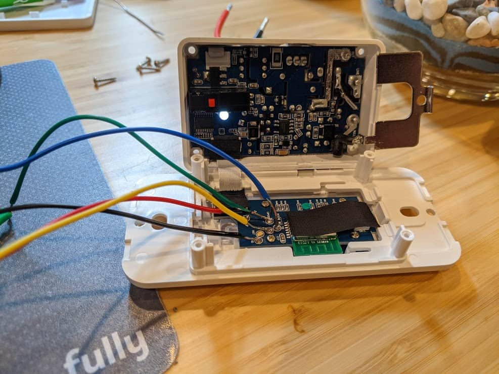
The Youngzuth 2-in-1 Switch is actually two switches that fit into the space of a single switch. When I opened the switch (Phillips head screwdriver) and started looking around the circuitboard, I couldn’t find any connection points for the serial interface. I finally hit the point I had been dreading… needing to solder directly to the chip.
The Youngzuth 2-in-1 uses a TYWE3S package and fortunately a lot of details are available on the Tuya Developer website, so it was pretty easy to figure our the chip connections. I really hate soldering, especially on tiny components next to other tiny components, so I had a margarita to steady my hand.
TYWE3S pin connections, colors showing all pins needed to reprogram
Once wires were connected, installing the software was a breeze. Configuration was also easy, with an example provided in the Youngzuth 2-in-1 template.
Full disclosure, I have not yet installed the Youngzuth switch, as I made a rookie mistake, not realizing there is no same-feed neutral connection at the switch location. Once installed I will post an update if anything required extra work.
If you have any questions or different experiences with these devices, please leave a reply below!
If you’ve ever had a free weekend, a desire to create a more secure smart home, and questionable judgment, you’ve come to the right place. In this post I’ll talk about how to take common IoT (Internet of Things) devices and put your own software on them.
Disclaimer: depending on the device, this exercise can range from pretty easy to drink bourbon and slam your head against the desk difficult. Oh, and there is some risk of electrocuting yourself or setting your house on fire. So everything after this point is for entertainment purposes only…
Why Hack Your IoT Devices?
Most people creating a smart home take the easy path… pick out some cheap and popular devices on Amazon, install the smartphone app to configure it, and are good to do. Why would anyone want to got through the extra effort to hack the device? There are a few good reasons:
Security: With few exceptions, most smart devices require installing an app on your phone, often times from an unknown vendor and with questionable device permissions needed. The devices themselves are tiny, wifi-connected computers, and also have software that is updated by connecting to a server in some country, and installing new software on the device connected to your home network. Having a cheap device connected to your home network that requires full access the Internet to work is bad, but it is worse when that software can be changed at any time, to do whatever the person changing it wants it to do. This could turn your light switch into part of a botnet, or worse, be exploited to attack other devices on your home network. By hacking replacing the software, you create a device that works properly without ever needing access to the Internet, lowing the security risk. You can also see (and change) exactly what software the device is using.
Sustainability: Since the devices require communicating with an external company for configuration and updates, when that company stops supporting the device or worse, goes out of business and turns off their servers, your device becomes useless or stuck in its current configuration forever. By hacking replacing the software, you are able to support the device even if the company ceases to exists. And by using open source software with a robust community, you will likely have very long term support.
Because I Can (mu ha ha ha): Okay, this is more of a fun reason, but worth mentioning. I’ve generally been much happier with the hacked versions of my products, whether it be my Tivo, Wii, or car dashboard. Smart light switches are a relatively low-risk hack, as they are inexpensive, and I’m assuming the risk is turning it into a brick, not causing an electrical fire (I’ll update the blog if I have an update on that).
Getting Started
My adventure started with the spontaneous purchase of a Gosund Smart Light Switch. Like a gazillion IoT devices sold by name brand and random manufacturers, this switch is controlled by an ESP8266. Most of these ESP8266 devices use a turnkey software solution made by Tuya, a Chinese company powering thousands of brands from Philips to complete randos.
For security and sustainability reasons, I decided I didn’t want this switch connected to my home network, and even if I wrote complex network firewall rules to limit its access, it would need to connect to the open Internet and other devices in my house to work properly.
I did some research and found Tasmota, an open source project that replaces the software on ESP8266 or ESP8285 devices, eliminating the need for Internet access and enabling functionality that make them easier to connect to controllers like Amazon’s Alexa. The older examples required disassembling the device and soldering to hack it, which is exactly not what I wanted to do. However, more recently there was an OTA (over the air) solution that didn’t require opening a device at all, and did all of the hacking over wifi… that sounded great.
Tasmota Wifi Installation
When I tinker I like to use a computer that I can reset easily so that I don’t have to worry about an odd configuration causing problems later. I have an extra Raspberry Pi that is handy for this, and installed a clean version of the Raspberry Pi Desktop to install on an extra Micro SD card.
I installed TUYA-CONVERT, which basically creates a new wifi network that and forges the DNS (how computers translate a name like tuya.com to numbers that identify a server) to resolve to itself rather than the Tuya servers, so that when the device goes to get a software update from the mothership, it gets the Tasmota software installed instead – hacking complete.
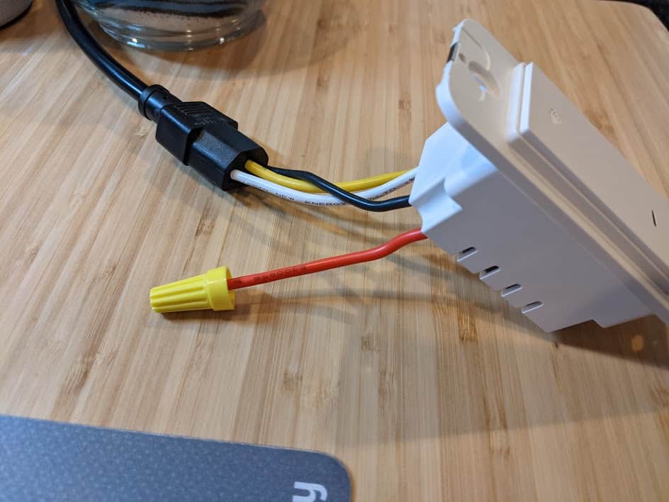
An example of poor judgment, however the red load wire is capped, as that is a not good wire to touch when the switch is on.
I started running the tuya-convert script on my Raspberry Pi and, rather than go through the full process of installing the switch in the wall, I found a standard PC power cable (C13) was the perfect size to hold the wires in place or allow testing on my desk. DO NOT DO THIS – I am showing you only as an example of what a person of questionable judgment might do. The switch powered up and on the tuya-convert console I could see it connecting and trying to get the new software! I love it when things just work.
But then, it didn’t work. While there was a lot of exciting communication happening between Raspberry Pi and the switch, ultimately the install failed. Looking at the logs, I was getting a message “could not establish sslpsk socket“, and found this open issue, New PSK format #483. Apparently, newer versions of the Tuya software require a secret key from the server to do a software update, and without the key (only known by Tuya), no new software will be accepted. So, damn… these newer devices can’t use the simple OTA update. Also, if you have older devices, do not configure them with the app it comes with if you plan on hacking, as that will update them from the OTA-friendly version to requiring the secret key.
Tasmota Serial Cable Installation
I realized I was too far down the rabbit hole to give up, so it was onto the disassembly and soldering option. The Tasmota site has a pretty good overview of how to do this, although I thought a no-solder solution would be possible, and tried to find the path that requires the least effort (yay laziness).
Gosund light switch SW5-V1.2 circuitboard, pen for scale. The connection points are the six dots towards the top, running down the right side (zoom in for labels).
Opening the switch required a Torx T5 screwdriver (tiny, star-shaped tool), and I happened to have one laying around from when I replaced my MacBook Pro battery. Looking at the circuit board, I realized that very tiny labels and contact points, combined with my declining eyesight, made this a challenge. I took a quick photo with my Pixel 4a and zoomed in to see what I needed… the serial connections on the side of the board (look for the tiny RX, TX, GND, and 3.3 labels… no, really, look). While soldering would be the most reliable connection, I was hoping test hook clips would do the job.
Since I was already using a Raspberry Pi, I didn’t need a USB serial adapter, as I could connect the Pi’s GPIO directly to the switch. Again, the Tasmota project has a page giving an example of connecting directly to the Pi. Whatever method you use, it is critical you connect with 3.3V, not 5V, and the higher voltage will likely fry the ESP8266. If you have a meter handy, check and double check the voltage. And, if you’re using the Raspberian OS, you may find /dev/ttyS0 is disabled… you will need to add enable_uart=0 to your /boot/config.txt file and reboot.
I connected the switch directly to the Raspberry Pi. There ware several things annoying about this, starting with each time the switch is connected to the 3.3V, it reboots the Pi. And since almost every command to the switch requires resetting its programming mode through a power cycle, that means rebooting the Pi frequently (fortunately it is a fast boot process).
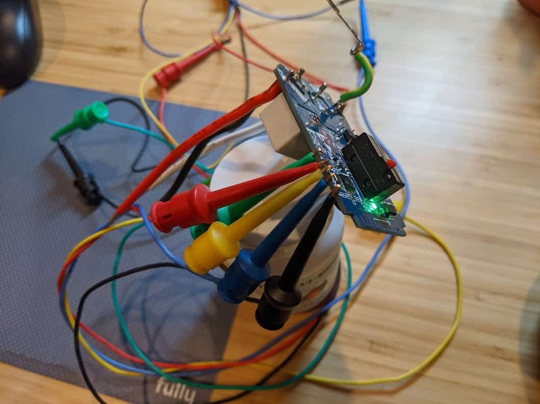
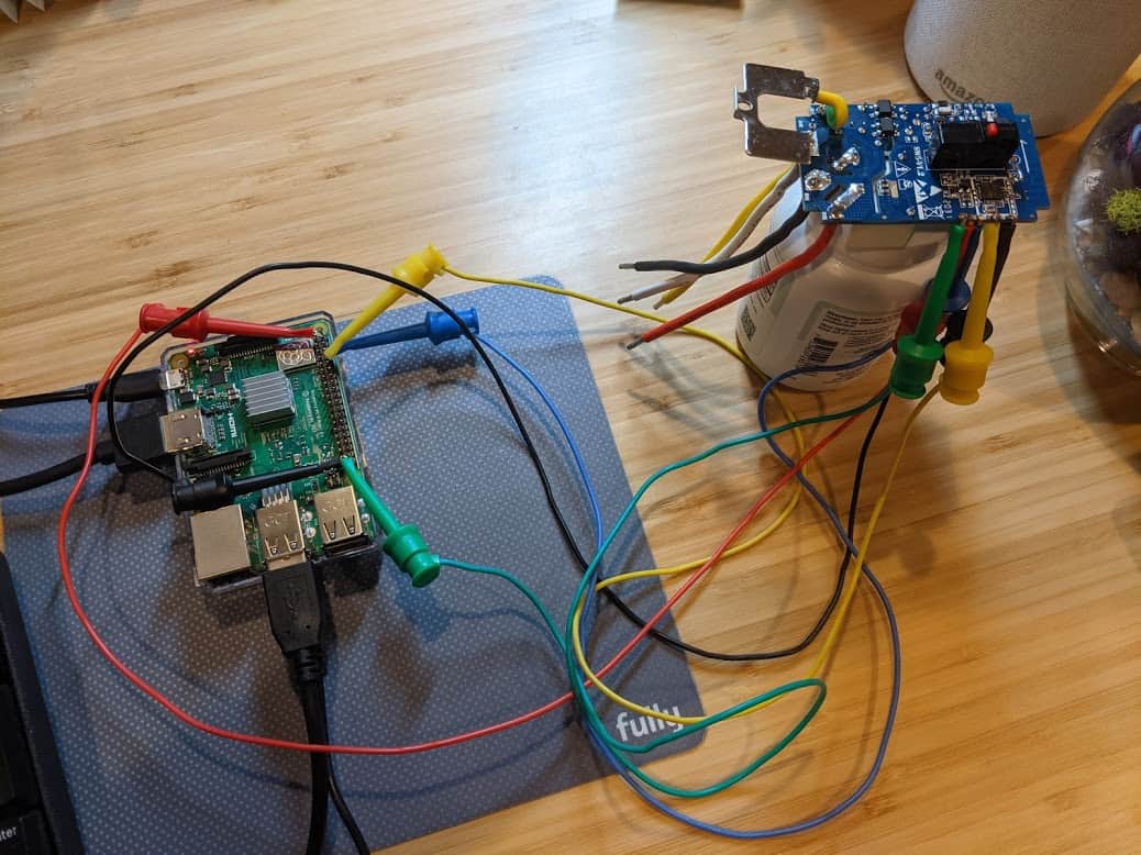
Test hook clips connecting the Raspberry Pi to the Gosund switch worked surprisingly well.
The good news is, the test hook clips worked, which was a bit of a surprise. I added a connection from Pi ground to switch 00 (green wire in the photo), as that forces the switch to enter into programming mode at boot (it is okay to leave that connected during the hacking process, or you can detach it once it is in programming mode). I made sure everything was precariously balanced to add excitement and more opportunities for failure into the process. I was able to confirm that I entered programming mode and had access to the switch by esptool, a command line utility for accessing ESP82xx devices. Success! 🎉
The bad news is, other than being able to read the very basics from the switch, like the chip type, frequency, and MAC address, pretty much everything else failed. And, each successful access only worked once and then required a reboot. I was unable to upload new software to the switch. After researching a bit, the best clue I had was problems with voltage drops on homemade serial devices, and wiring directly to the Pi circuitboard seemed like it might apply. At this point I needed a drink, and went with a nice IPA.
But hey, once you’re this far down the rabbit hole, why stop? I decided to try a more traditional serial connection, using a CH340G USB to serial board.
Serial Killer Part Two
Apparently there was an issue using the Raspberry Pi directly for the serial communication as the USB to serial adapter worked perfectly. I validated the connection using esptool and then used the tasmotizer GUI, which makes it easy to backup, flash, and install new software on the switch. Many steps require rebooting the switch to proceed to the next step, but that is as simple as unplugging the USB cable and plugging it back in (even better that it isn’t triggering a reboot of the Raspberry Pi each time).
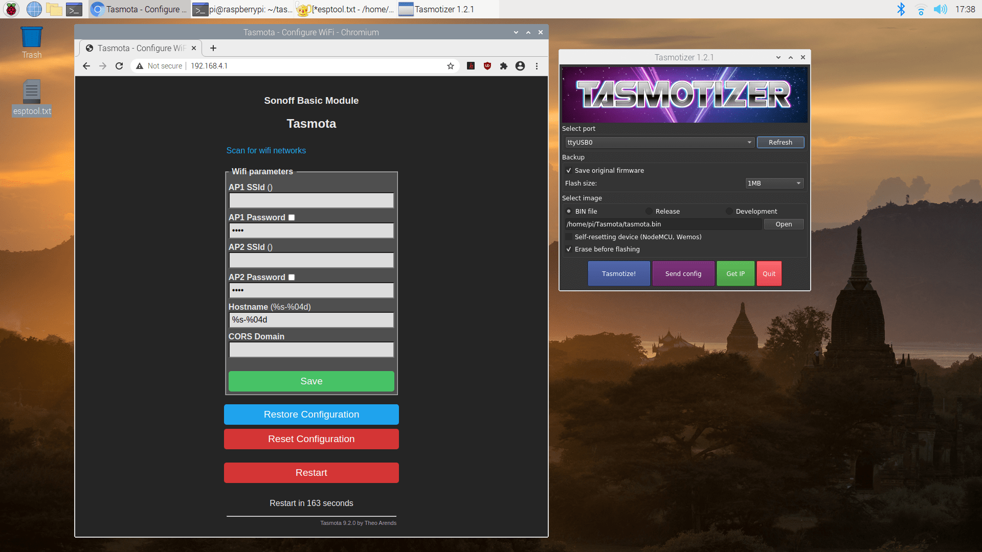
Tasmotizer and the default web interface to configure your newly-hacked switch
Once the new software is installed, there is one final reboot of the switch (don’t forget to disconnect the ground to 00 or else it boots back into programming mode). At this point the switch sets up a wifi network names tasmota[mac] where [mac] is part of the mac address. Connect to this network and point your browser to http://192.168.4.1 and you are able to configure your device. Set AP1 SSId and AP1 Password to your home wifi, click “save”, and a few seconds later your switch will be accessible from your home network.
If you’re curious about attempting this yourself, have questions about my sanity, or have other experiences hacking your smart devices, I’d love to hear from you – please leave a reply below!
I have an early 1990’s garage door opener that does all of the things you need a garage door opener to do (it… opens the garage door). However, the remotes are the size of cinder blocks and I never have one with me when I need it, so I decided to find a way to use my phone instead. This project is part of a long history of unnecessarily connecting items in my house to the Internet.
Requirements
A janky garage door opener, ideally the kind with wired switches attached to your garage wall
Some form of a server… nothing powerful. A $50 Raspberry Pi is about 50x more powerful than you need
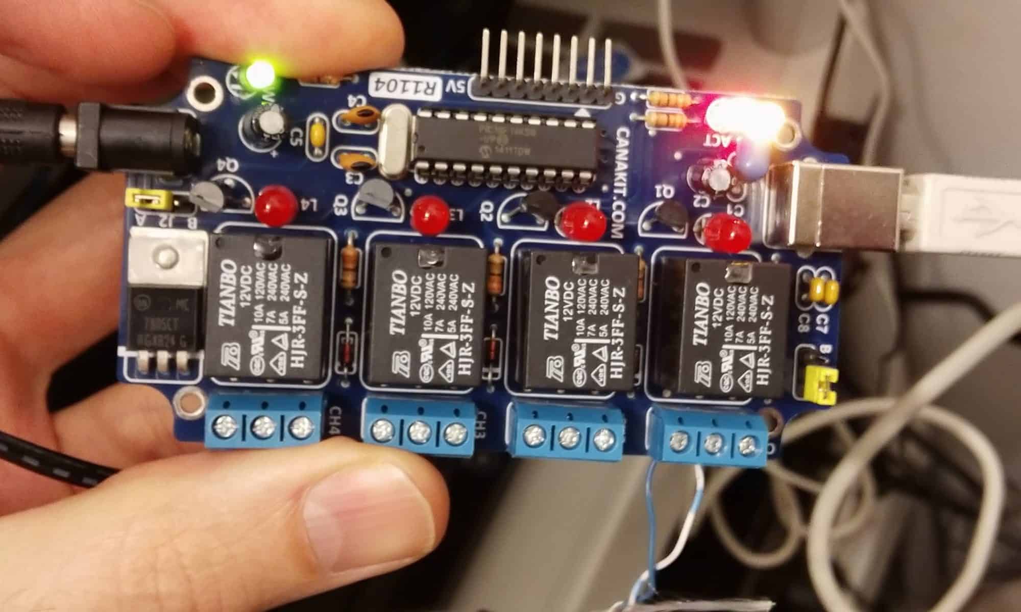
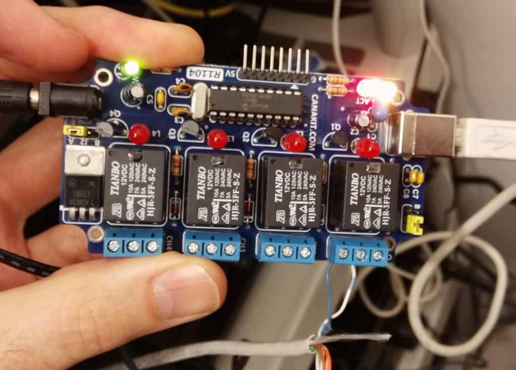
A relay controller. For this project I happened to have a CanaKit UK1104 USB relay controller laying around
Some wire to connect from your server to the garage door opener, CAT5 is overkill and works great
A patient / forgiving significant other
Installation
Wait for your significant other to leave the house for at least 90 minutes.
Connect the relay controller to your server
Grab my Garage-Door-Controller code from Github and copy it into the html directory of your server. In includes PHP and Perl scripts, the best programming languages 😜
Install the Perl package Device::SerialPort. On Ubuntu / Debian: sudo apt-get install libdevice-serialport-perl
Make sure the script can access the serial device… On Linux, you can add the web user www-data to the dialout group, or if you want a less secure option, use visudo and add this line: www-data ALL=(root) NOPASSWD: /var/www/html/garage/garageinterface (use the path for your server)
Make sure the file garageinterface is executable, chmod a+x garageinterface
Run a wire from the relay 1 on the controller to the same terminals on your garage door that the buttons on your wall are connected to (you can leave those wires in place, too… no need to make the buttons not work). On your relay, the wires should connect to “COM” and “NO” (common and normally open)
Opening Your Garage Door
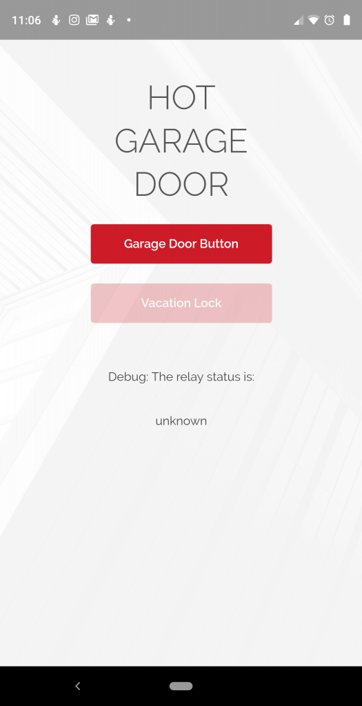
When connected to the same network as your server, simply point your web browser to /garage and the magic begins. If you are using your phone browser, the “Add to Home Screen” option creates an icon on your phone and eliminates the menu bar, making a clean interface.
It’s… pretty simple
The scripts provide a simple web interface that is responsive (it automatically adjusts to the screen where it is being rendered), so it works well on a phone web browser or whatever other web-capable device you want to use to open your garage..
There is a single “Garage Door Button” and pressing it… that’s right… it does the same thing as if you pressed the button connected to your garage door opener.
Of course you can connect the relay to whatever else you want to control… lights, refrigerators, bug zappers, sprinklers, your toaster.
Security Concerns
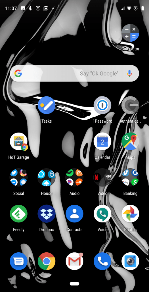
The HoT Garage “app” on my home screen.
If you are silly enough to follow in my path, I strongly suggest you only run this on a local home network (e.g. you must be connected to your home wifi) if you are using it on something like a garage door, partially because I didn’t consider security at all when writing the scripts, and more importantly, why in the hell would you want to open your garage door when you are not near your garage door? I know it sounds cool, but… no.
Happy Tinkering!
If you have a habit of wiring things up to teh Interwebs, I’d love to hear about your experiences… especially the ones that didn’t work out exactly as planned. Please leave a reply, below!