
If you’ve ever had a free weekend, a desire to create a more secure smart home, and questionable judgment, you’ve come to the right place. In this post I’ll talk about how to take common IoT (Internet of Things) devices and put your own software on them.
Disclaimer: depending on the device, this exercise can range from pretty easy to drink bourbon and slam your head against the desk difficult. Oh, and there is some risk of electrocuting yourself or setting your house on fire. So everything after this point is for entertainment purposes only…
Why Hack Your IoT Devices?
Most people creating a smart home take the easy path… pick out some cheap and popular devices on Amazon, install the smartphone app to configure it, and are good to do. Why would anyone want to got through the extra effort to hack the device? There are a few good reasons:
- Security: With few exceptions, most smart devices require installing an app on your phone, often times from an unknown vendor and with questionable device permissions needed. The devices themselves are tiny, wifi-connected computers, and also have software that is updated by connecting to a server in some country, and installing new software on the device connected to your home network. Having a cheap device connected to your home network that requires full access the Internet to work is bad, but it is worse when that software can be changed at any time, to do whatever the person changing it wants it to do. This could turn your light switch into part of a botnet, or worse, be exploited to attack other devices on your home network. By
hackingreplacing the software, you create a device that works properly without ever needing access to the Internet, lowing the security risk. You can also see (and change) exactly what software the device is using. - Sustainability: Since the devices require communicating with an external company for configuration and updates, when that company stops supporting the device or worse, goes out of business and turns off their servers, your device becomes useless or stuck in its current configuration forever. By
hackingreplacing the software, you are able to support the device even if the company ceases to exists. And by using open source software with a robust community, you will likely have very long term support. - Because I Can (mu ha ha ha): Okay, this is more of a fun reason, but worth mentioning. I’ve generally been much happier with the hacked versions of my products, whether it be my Tivo, Wii, or car dashboard. Smart light switches are a relatively low-risk hack, as they are inexpensive, and I’m assuming the risk is turning it into a brick, not causing an electrical fire (I’ll update the blog if I have an update on that).
Getting Started
My adventure started with the spontaneous purchase of a Gosund Smart Light Switch. Like a gazillion IoT devices sold by name brand and random manufacturers, this switch is controlled by an ESP8266. Most of these ESP8266 devices use a turnkey software solution made by Tuya, a Chinese company powering thousands of brands from Philips to complete randos.
For security and sustainability reasons, I decided I didn’t want this switch connected to my home network, and even if I wrote complex network firewall rules to limit its access, it would need to connect to the open Internet and other devices in my house to work properly.
I did some research and found Tasmota, an open source project that replaces the software on ESP8266 or ESP8285 devices, eliminating the need for Internet access and enabling functionality that make them easier to connect to controllers like Amazon’s Alexa. The older examples required disassembling the device and soldering to hack it, which is exactly not what I wanted to do. However, more recently there was an OTA (over the air) solution that didn’t require opening a device at all, and did all of the hacking over wifi… that sounded great.
Tasmota Wifi Installation
When I tinker I like to use a computer that I can reset easily so that I don’t have to worry about an odd configuration causing problems later. I have an extra Raspberry Pi that is handy for this, and installed a clean version of the Raspberry Pi Desktop to install on an extra Micro SD card.
I installed TUYA-CONVERT, which basically creates a new wifi network that and forges the DNS (how computers translate a name like tuya.com to numbers that identify a server) to resolve to itself rather than the Tuya servers, so that when the device goes to get a software update from the mothership, it gets the Tasmota software installed instead – hacking complete.
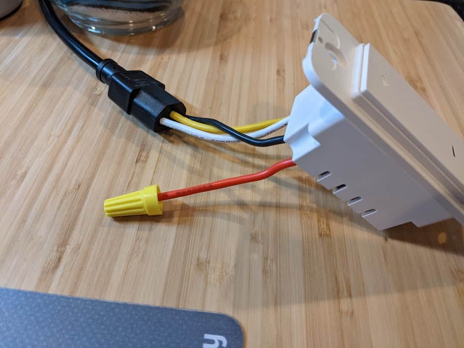
I started running the tuya-convert script on my Raspberry Pi and, rather than go through the full process of installing the switch in the wall, I found a standard PC power cable (C13) was the perfect size to hold the wires in place or allow testing on my desk. DO NOT DO THIS – I am showing you only as an example of what a person of questionable judgment might do. The switch powered up and on the tuya-convert console I could see it connecting and trying to get the new software! I love it when things just work.
But then, it didn’t work. While there was a lot of exciting communication happening between Raspberry Pi and the switch, ultimately the install failed. Looking at the logs, I was getting a message “could not establish sslpsk socket“, and found this open issue, New PSK format #483. Apparently, newer versions of the Tuya software require a secret key from the server to do a software update, and without the key (only known by Tuya), no new software will be accepted. So, damn… these newer devices can’t use the simple OTA update. Also, if you have older devices, do not configure them with the app it comes with if you plan on hacking, as that will update them from the OTA-friendly version to requiring the secret key.
Tasmota Serial Cable Installation
I realized I was too far down the rabbit hole to give up, so it was onto the disassembly and soldering option. The Tasmota site has a pretty good overview of how to do this, although I thought a no-solder solution would be possible, and tried to find the path that requires the least effort (yay laziness).

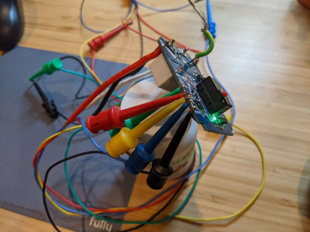
Opening the switch required a Torx T5 screwdriver (tiny, star-shaped tool), and I happened to have one laying around from when I replaced my MacBook Pro battery. Looking at the circuit board, I realized that very tiny labels and contact points, combined with my declining eyesight, made this a challenge. I took a quick photo with my Pixel 4a and zoomed in to see what I needed… the serial connections on the side of the board (look for the tiny RX, TX, GND, and 3.3 labels… no, really, look). While soldering would be the most reliable connection, I was hoping test hook clips would do the job.
Since I was already using a Raspberry Pi, I didn’t need a USB serial adapter, as I could connect the Pi’s GPIO directly to the switch. Again, the Tasmota project has a page giving an example of connecting directly to the Pi. Whatever method you use, it is critical you connect with 3.3V, not 5V, and the higher voltage will likely fry the ESP8266. If you have a meter handy, check and double check the voltage. And, if you’re using the Raspberian OS, you may find /dev/ttyS0 is disabled… you will need to add enable_uart=0 to your /boot/config.txt file and reboot.
I connected the switch directly to the Raspberry Pi. There ware several things annoying about this, starting with each time the switch is connected to the 3.3V, it reboots the Pi. And since almost every command to the switch requires resetting its programming mode through a power cycle, that means rebooting the Pi frequently (fortunately it is a fast boot process).
The good news is, the test hook clips worked, which was a bit of a surprise. I added a connection from Pi ground to switch 00 (green wire in the photo), as that forces the switch to enter into programming mode at boot (it is okay to leave that connected during the hacking process, or you can detach it once it is in programming mode). I made sure everything was precariously balanced to add excitement and more opportunities for failure into the process. I was able to confirm that I entered programming mode and had access to the switch by esptool, a command line utility for accessing ESP82xx devices. Success! 🎉
The bad news is, other than being able to read the very basics from the switch, like the chip type, frequency, and MAC address, pretty much everything else failed. And, each successful access only worked once and then required a reboot. I was unable to upload new software to the switch. After researching a bit, the best clue I had was problems with voltage drops on homemade serial devices, and wiring directly to the Pi circuitboard seemed like it might apply. At this point I needed a drink, and went with a nice IPA.
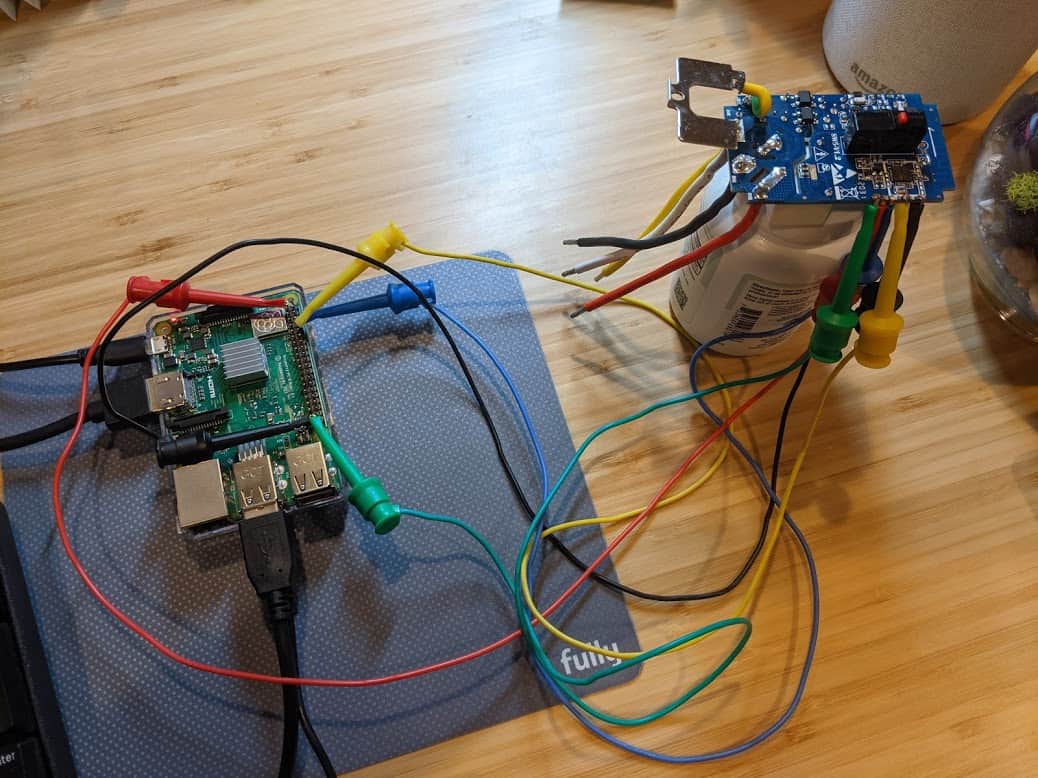
But hey, once you’re this far down the rabbit hole, why stop? I decided to try a more traditional serial connection, using a CH340G USB to serial board.
Serial Killer Part Two
Apparently there was an issue using the Raspberry Pi directly for the serial communication as the USB to serial adapter worked perfectly. I validated the connection using esptool and then used the tasmotizer GUI, which makes it easy to backup, flash, and install new software on the switch. Many steps require rebooting the switch to proceed to the next step, but that is as simple as unplugging the USB cable and plugging it back in (even better that it isn’t triggering a reboot of the Raspberry Pi each time).
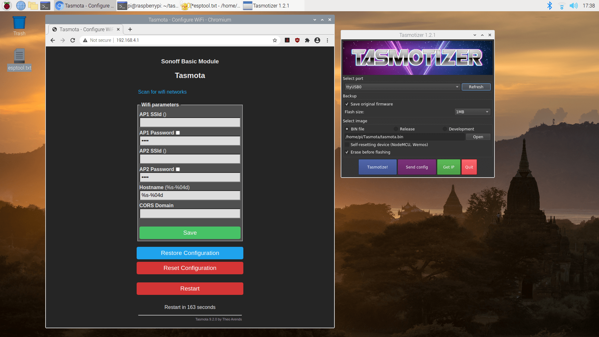
Once the new software is installed, there is one final reboot of the switch (don’t forget to disconnect the ground to 00 or else it boots back into programming mode). At this point the switch sets up a wifi network names tasmota[mac] where [mac] is part of the mac address. Connect to this network and point your browser to http://192.168.4.1 and you are able to configure your device. Set AP1 SSId and AP1 Password to your home wifi, click “save”, and a few seconds later your switch will be accessible from your home network.
I’ll provide the details of configuration in a follow-up post, but I used the Gosund SW1 Switch template following these instructions to import it, and turned on “Belkin WeMo” emulation to make the switch automatically discoverable by Alexa, without the need to install special apps on my phone or skills on Alexa. The configuration process and connecting to Alexa was incredibly easy and took less than 5 minutes.
Update January 2, 2020: I added a post on hacking the Gosund Smart Dimmer Switch (SW2) and the Youngzuth 2-in-1 Switch, each of which required a different technique.
If you’re curious about attempting this yourself, have questions about my sanity, or have other experiences hacking your smart devices, I’d love to hear from you – please leave a reply below!
wow
Any clue as to what the protocol is of these devices? I’m having trouble finding out how to just connect to them like the phone app does and send whatever code it needs to turn things on and off, control a dimmer, etc.
If you are asking about the wired connection (from your USB or serial port to the device), it is just a standard serial connection, like using a terminal to connect to a modem. If you are asking about the wireless protocol, there is likely common software being used, but it is proprietary, and possibly dependent on a remote server (most devices since ~2020 require a digital signature from the manufacturer to replace the software)