With the SunPower bankruptcy and many users being left with no great support options (unless they pay a subscription), I am getting more and more people landing and commenting on my earlier SunPower PVS6 posts. So, I’m providing an update for what I recommend today, and I am including some (maybe a little janky) pages for self monitoring.
Disable SunPower / SunStrong Access
The first thing I am going to suggest, disconnect your PVS6 from your Internet, either by disabling the wifi in the app or, even better, block it with a firewall rule. Why? Well, the only changes SunStrong seems to be making is locking owners out of their PVS6 and adding subscription options to get to your data. So while you can still get access to your PVS6 today, that could change if they do future updates to block you. So, block them. Yeah, you won’t have access to “most recent power” in the SunStrong app but that isn’t too useful anyway and everything else seems to be an upsell.
Take Control
The next thing you need is local access to your PVS6. I documented some of this in Very Basic SunPower and Home Assistant, no HACS, but the basic idea is there is an Internet port in your PVS6 and you need to connect it to your home network. I provided one solution, but there are many ways to go about it.
Once you have access, you can easily hook up your internal home management systems, like Home Assistant with the hass-sunpower integration (both free).
A Free, No Server Monitoring Solution
I built a very basic monitoring webpage that you can run from your computer, no server needed. And by “built”, it was pure vibe coding – don’t install it on a publicly accessible server as, like fruitcake, I’m not 100% sure what’s in it.
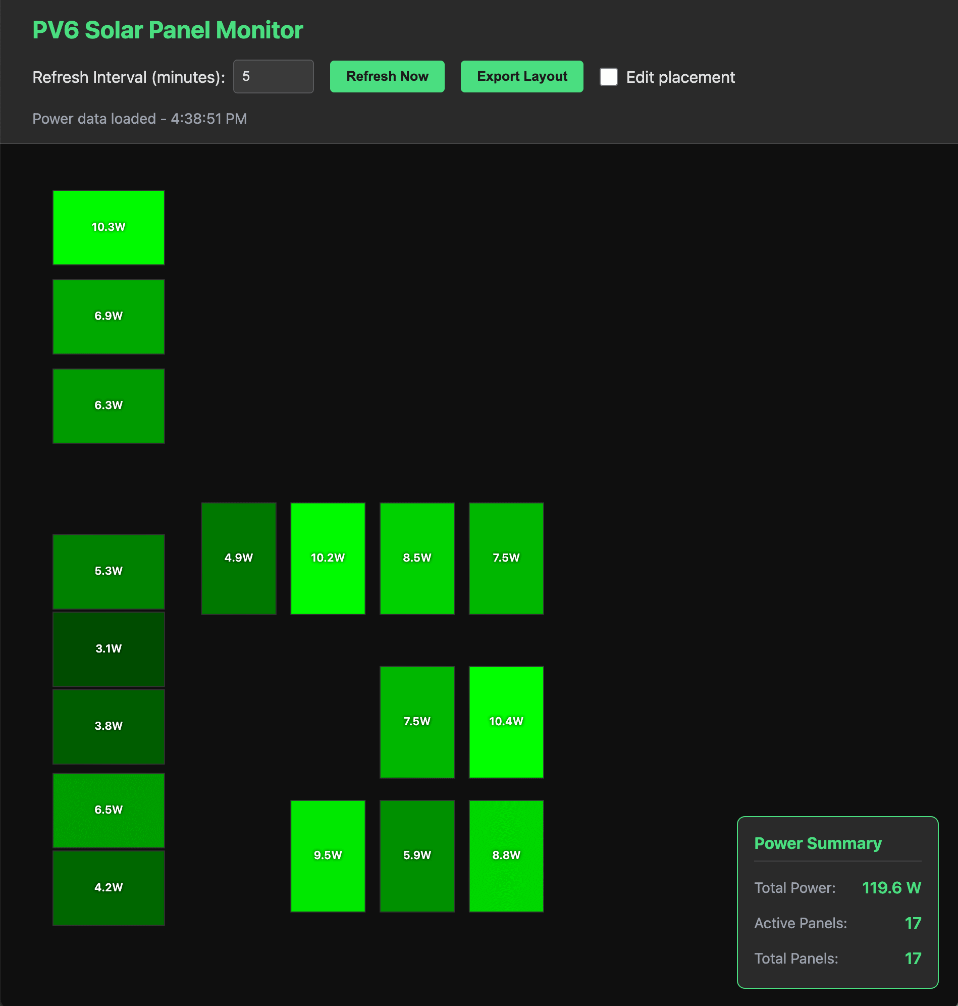
SunPower PVS6 Monitoring App, almost night time
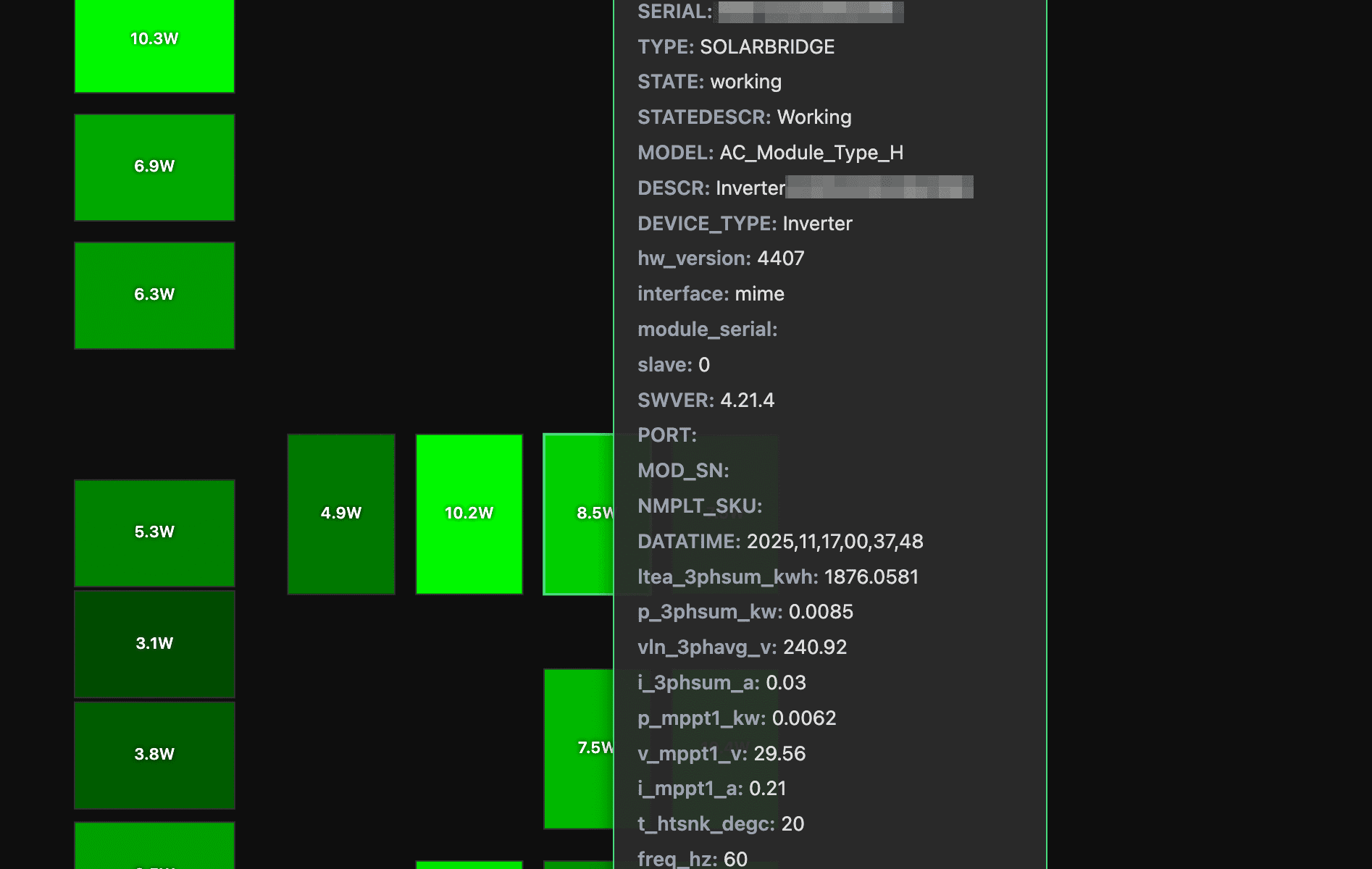
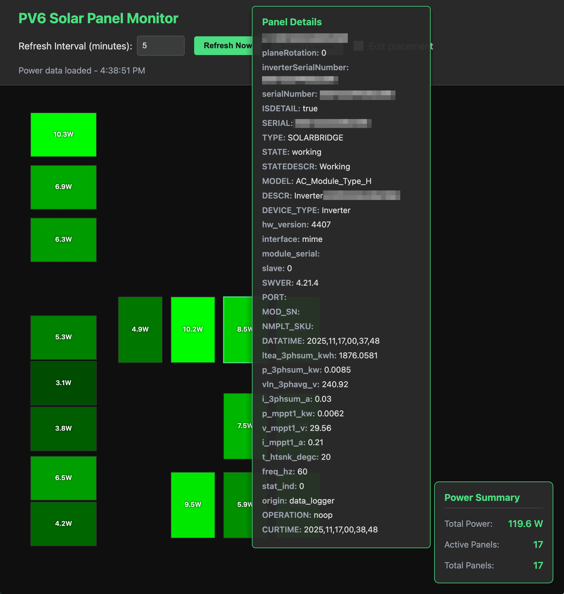
The basic functionality is pretty simple… set a config file to your PVS6 and it will read your panel information (including physical locations – who knew those were in the PVS6 settings?) and then show you the real-time power generation of each panel. And if you want to dig in deeper, all of the panel information can be examined with a simple mouse over. Each panel is shown brighter based on the power it is generating.
If the panel layout isn’t what you expect you can also drag the panels to your preferred locations. That said, the layout for my house just… sort of worked. Your milage may vary.
Oh, since the panel locations don’t change, you can export your layout and speed up access every time you load the web page (yes, do this).
How do you use it? Download from GitHub and just click on the index.html file (well, look at the README.md file to configure it to point to your PVS6 first).
SunPower PVS6 Detailed panel view (again, almost night time)
I’ve tested this on all of one system – mine. So I am sure there are many edge cases that don’t work, but I’m happy to work through some bugs / enhancements as I get some time.
Did you try it? Love it? Hate it? Want a feature or bug fix? Please leave a comment, below!
The Winnebago Solis 59P comes with two Group 31 AGM batteries for running the house power and eventually, those batteries are going to need to be replaced. I found that it seems to be possible to replace these with LiFePO4 batteries, which likely have some advantages.
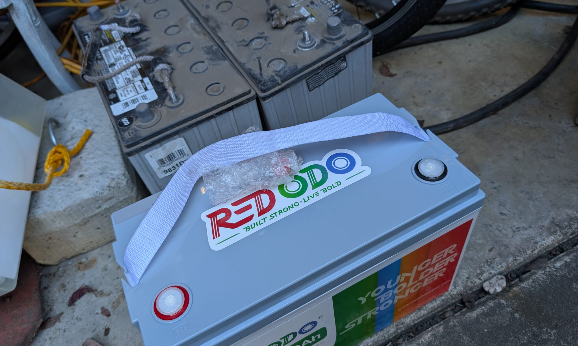
I won’t go into to many details, but AGM (absorbed glass-mat) batteries are lead acid batteries that are sealed, don’t require maintenance, and don’t need to be upright. Oh, and the Group 31 size that the Solis takes are heavy AF. LiFePO4 (or LFP) batteries are made of lithium iron phosphate, and also don’t require maintenance. The have longer lifetimes, more cycles, charge quickly, and have slower self discharge. And… they weight about 25% of the AGM battery. The downside? Traditionally they are way more expensive. However, when looking for replacement AGM batteries, I found these Redodo LiFePO4 batteries were as inexpensive as some of the least expensive AGM batteries, so these are a clear win! Well, assuming they work.
As far as I could tell. the things to consider in swapping the battery types are the WFCO WF-8955PEC power center that handles the conversion of power from when you plug in to AC, and the Xantrex Solar Charge Controller 30 that charges batteries using solar from the solar panels. The Xantrex was pretty simple to work out, there is a setting for LFP batteries, so you just need to change that and life is good. Unfortunately, the website for WFCO power center states that it is not a lithium ready solution and directs one to a new power center purchase. However, I stumbled upon this post suggesting that the 8955PEC specs are comparable with LiFePO4 charging requirements, so I decided to let go, let Glob and take the plunge.
Physical Battery Replacement
rustic jack stands
The house batteries are underneath the Solis on the rear right, and I was able to get enough access to work by driving onto two rows of bricks (rustic jack stands). Taking the old batteries out was a struggle only because of the weight (see “heavy AF”, above) and my pinky is still healing from being crushed against the concrete as the first battery came out of the tray. Once out, it was time to install the brand new LiFePO4 batteries…
First, OMG dealing with the LiFePO4 batteries was a dream compared to the AGMs, as they have about 25% of the weight. They were way easier to lift, position, and manipulate. The only challenge in installing the new batteries was the post bolts are a little short and the front battery has three leads on the positive terminal, so lining up all connectors on thick cables coming from different angles took some effort.
Finally connected, tightened up, and secured, I enabled the house power and… let there be light! As far as the basic, you have one job, supply power aspect, everything seemed to work. I changed the battery type on the solar charge controller to LFP and, we’re done! Hopefully.
Diagnostics
The bar was pretty low of my first diagnostic test… do the LiFePO4 batteries power the Solis? Yep, they do.
While I purchased the same model battery for each replacement, one of the batteries I purchased has bluetooth capability, so I was also able to confirm a few other things. For one, the batteries do go into a “charging” state from the solar panels even when the main house power is turned off (I’ve seen conflicting posts on whether house power needs to be on for the batteries to charge). I also confirmed that with the house power off at night, the battery in an idle state (no power in or out), so that seems right.
Oh, I also verified that my Solis has not spontaneously combusted, which is also a good sign.
There a few other things I need to test and I’ll update this posting when I have more results (or share photos of a Solis on fire).
First, I need to test charging from AC. I almost always do dry camping, so I need to run special test for this, and I think this relies on the WFCO power center to do the right thing, so there is some risk it won’t do what I’m hoping.
Additionally, I need to test the charge from the van’s electrical system (when I a driving, does it charge the batteries properly).
Finally, I need to do a little more research on the LiFePO4 lifecycle and ensure the charging / discharging patterns are doing all the things to ensure the optimal lifespan.
Been here, done this or have other suggestions for me? I’d love to hear about it and learn from your experiences…please leave a comment, below!
If you’ve ever wanted to see a figurine of yourself but you have no artistic talent, AI image generation can make that dream come true, and you can try it for free. I jump right into the “how to” and add my boring commentary to the end of this post, so you can skip it.
Brett, in real life
I’m using DALL-E for my image generation which requires a paid subscription, but you can get free access to it through Microsoft Bing Image Creator (requires a free Microsoft account). Once you have signed in, look for the text input field next to the two buttons “Create” and “Surprise Me”. The text field is where you describe what image you want AI to generate, then you click “Create” and a few seconds (or minutes) later, up to four images will be displayed. This process is called “prompting”, which is a common way to guide AI to generate the desired output. But getting AI to do exactly what you want is a little like herding drunk cats, so crafting the prompt can take some effort and some understanding of how things work under the hood. We’ll skip that for now and just start making fun things…
Anime figurine Brett with laptop and margarita
The structure for the prompt is “Anime figurine of <my description, skin tone, eye color, hairstyle, outfit>. The figurine is displayed inside a box with <text on box> and logo for the box, allowing visibility of the figure, typography, 3D render”. To make something that looks sort of like me, I used “Anime figurine of a shaved head, bald on top, nerd, white skin tone, dark gray hair, blue eye color, brown short beard, brown eyebrows, black shirt, jeans, Converse high tops, wearing blue rimmed glasses, wearing a watch, holding a laptop and a margarita. The figurine is displayed inside a box with Brett and logo for the box, allowing visibility of the figure, typography, 3D render“
AI reminding Brett of what he lost
Once you’ve tried this for yourself, you probably noticed a few things… Most obviously, somehow the AI didn’t do what you thought you told it. For example, while I prompted “bald on top“, one of my images clearly had hair, which might be the AI getting confused with the conflicting “dark gray hair” in the prompt. I have found replicating hairstyles, even bald hair styles (if… that’s a hair style?), can be challenging. I’ve yet to be able to get any consistency with hair only on the sides and back of the head. The other thing you will probably notice is the wild things that can show up in the image, especially when it comes to text generation, where AI tends to get… creative. Some of the words you use in your prompt may show up in the image, and misspelling is not uncommon.
Cheers!
There is considerable variation in the images, some looking more like the giant-headed Funko Pop figurines, and others having pretty realistic proportions. Prompting for another common outfit I wear, “Anime figurine of a shaved head, bald on top, nerd, white skin tone, dark gray hair, blue eye color, brown short beard, brown eyebrows, black shirt, tan pants, brown leather boots, wearing blue rimmed glasses, wearing a watch, holding a laptop and a pint of beer. The figurine is displayed inside a box with Brett and logo for the box, allowing visibility of the figure, typography, 3D render” created something a little more proportional.
Funko Pop Brett
So play around a little and see what you get… if anime isn’t your thing and you really love the Funko Pop style, try swapping out the prompt, “Funko style figurine of a shaved head, bald on top, nerd, white skin tone, dark gray hair, blue eye color, brown short beard, brown eyebrows, black shirt, jeans, Converse high tops, wearing blue rimmed glasses, wearing a watch, holding a laptop and a margarita. The figurine is displayed inside a box with Brett and logo for the box, allowing visibility of the figure, typography, 3D render“.
This gallery contains more examples:
Boring Commentary
A little over a year ago I wrote Robots Building Robots: AI Image Generation, where I used my laptop for AI image generation, meaning I had to use substantially less powerful AI models than are available in the cloud, where processing power and memory can be massive. The less powerful model was fine for the specific application I had in mind (a cartoon-like sketch of a robot for a sticker), but a few people commented that the quality of the AI images was average, and some were skeptical about AI’s capability.
In that same post, I mentioned Midjourney, which at the time version 4 was just coming out and already looking pretty amazing. In the 14 months since then, the quality and capability has continued to improve at an astonishing pace. For a detailed look at Midjourney specifically, check out this post from Yubin Ma at AiTuts. In less than two years, this model has gone from distorted human faces (some almost unrecognizable) to photo realism.
Female knight generated by Midjourney, V1 (Feb 2022), V4 (Nov 2022), V6 (Dec 2023), images from AiTutsVintage photo of girl smoking generated by Midjourney, V1 (Feb 2022), V4 (Nov 2022), V6 (Dec 2023), images from AiTuts
I have been surprised by both the rate at which the quality and the versatility of AI generated images has increased, with the anime figurines being one of the more recent (and delightful) examples of something AI can create unexpectedly well. I’m limiting this post to still image generation, but the same is happening for music, video, and even writing code (my last three hobby programming projects were largely created by AI). It’s reasonable to assume that AI will make substantial improvements to generating 3D image files, so soon you’ll be able to 3D print your cool little anime figurine.
There are, of course, significant implications of having computers provide a practical alternative to work that used to require humans, and much like the disappearance of travel agents once the Internet democratized access to booking travel, we should expect to see a dramatic reduction in demand for human labor, and this will be disruptive and upsetting… some professions will be nearly eliminated. I don’t want to be dismissive about the human impact of more powerful automation.
At the same time, AI can empower people, and create entirely new opportunities. Large language models (LLM) create the opportunity for customized learning, where eventually individuals all across the planet can have a dialog with an AI teacher, navigating millions of human years of knowledge. More and more, people will not be limited by their resources, they will only be limited by their ideas… The average person will be able to build a website, or a phone app by describing what they want, and someone considering themselves as “not artistic” will be able to create songs, artwork, or even movies that will eventually be box office quality. AI will also likely play a significant role in things like medical advances and energy efficiency, things we generally consider good for humans.
Did you enjoy making yourself into an anime figurine? Did you come up with a prompt that made a super cool image? Did you figure out how to get my male pattern baldness accurate on the figurine? This my hot take on being optimistic about AI is horrible? Leave a comment, below!
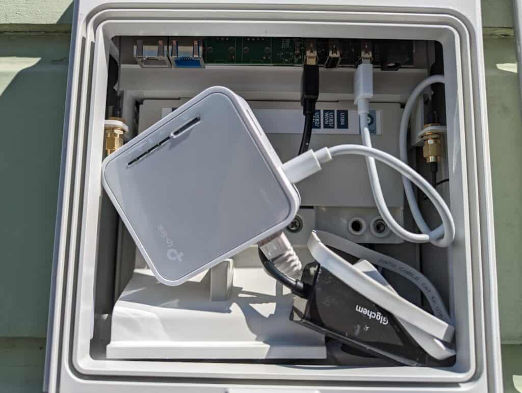
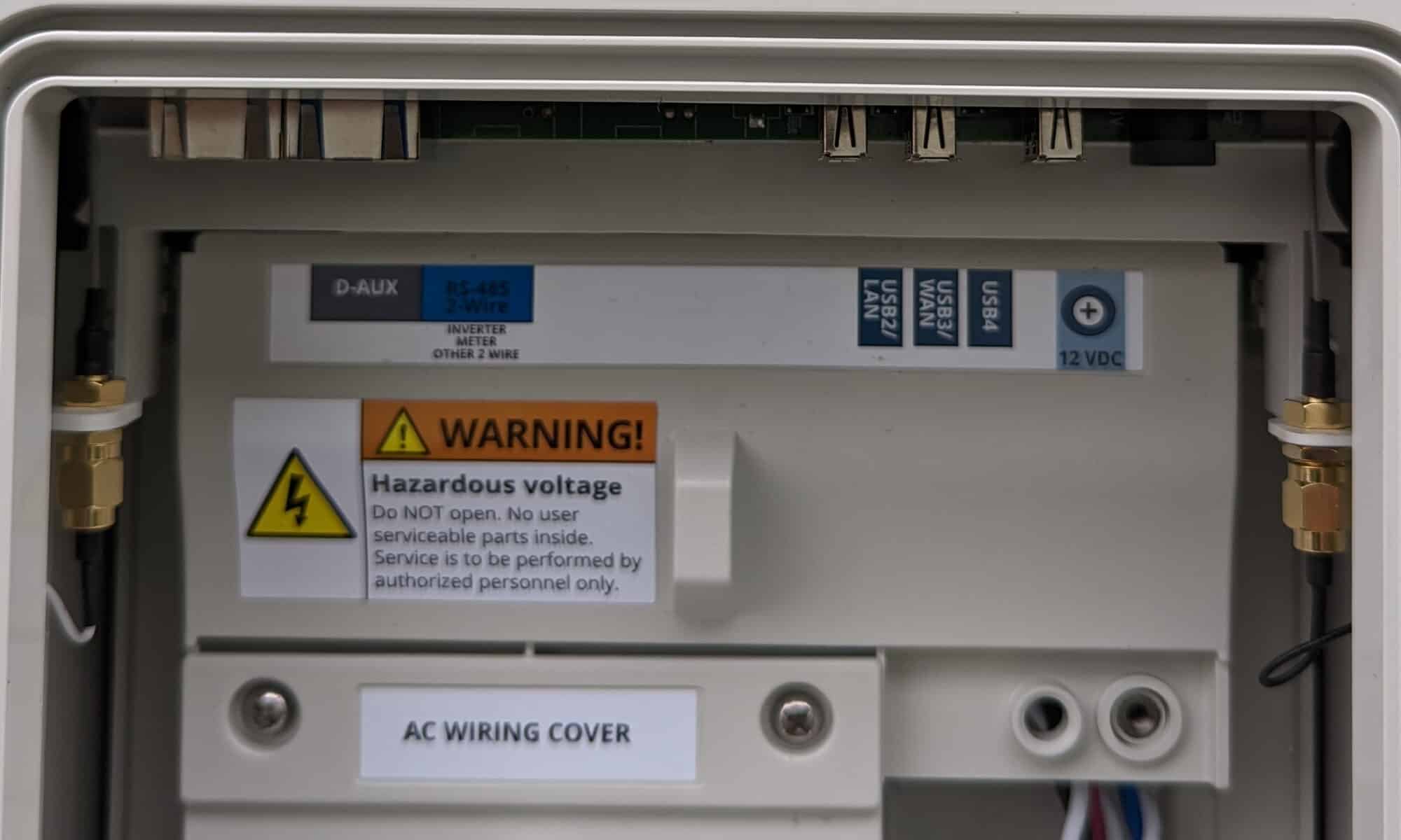
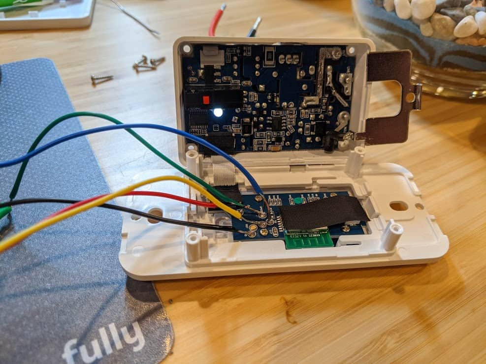
The first thing was getting the SunPower PVS6 administrative interface. Since I didn’t have easy cabling access, I used a $7 ethernet adapter and a TP-Link AC750 Wireless Portable Nano Travel Router (TL-WR902AC). There is a cheaper model of the TP-Link that would have worked just fine, but even at $39 it was less expensive than most of the lowest-end Raspberry Pi crazy-ass prices right now. Power for the TP-Link comes from the LAN4 port on the PVS6, and the ethernet connects to USB2/LAN. The TP-Link is configured in “Router Mode”, where it connects by wired ethernet to the PVS6 and creates a separate network for all devices that connect by wifi. If you do this, you will want to configure the TP-Link to use a network different than your home network (e.g. if your home network is 192.168.0.0/24, use something like 192.168.2.0/24).
TP-Link and ethernet dongle crammed in the SunPower PVS6
At this point you should be able to connect to the TP-Link wifi and test access to the administrative interface at http://172.27.152.1.
Of course, the problem now is we need to connect the home network to the SunPower network, but there is some nuance… we only want the web traffic. Very specifically, we do not want the TP-Link to connect to the network and start giving new IP addresses to our home network, which is also why you don’t just plug the ethernet from the PVS6 into your home network.
I happen to have a home file / everything else server that runs on a Raspberry Pi, and already has Apache running. That server connects to my home network via an ethernet cable, so its wifi was unused and available. I connected to the SunPower wifi (SSID “sunpowernet”):
sudo nmcli d wifi connect sunpowernet password "5ekr1tp@$$"
Finally, I need to let the server know that when the destination network is the PVS6, it needs to use the wifi connection, not the ethernet connection:
sudo ip route add 172.27.152.0/24 via 192.168.2.1
This is a great time to mention that it would be good hygiene to setup your server to have firewall rules blocking incoming traffic from the TP-Link, other than DHCP and established connections, in case the PVS6 is ever compromised.
Reverse Proxy
While HAProxy is super awesome and you should absolutely use it if starting from scratch, I happen to have a home server that gets 5 requests per month and was already running Apache, so I wanted to do as little extra work as possible. Fortunately, Apache has a reverse proxy, and that makes this pretty easy. I setup a virtual host with the following sunpowerproxy.conf config:
The virtual server is going to expect the HTTP request to come to a server named “sunpowerproxy” (or whatever you name it), so you’ll need to add that DNS entry pointing to the ethernet address, not the wifi address.
After a few seconds you should get a JSON blob listing all of your devices.
Home Assistant Configuration
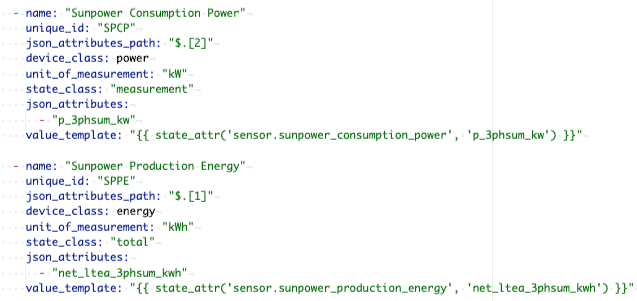
Finally, we need Home Assistant to be able to pull the values from the proxy. The RESTful integration provides a pretty easy way to do this… here is a basic configuration to get the current power usage and overall energy, although a lot more information, including details for each individual panel, is available:
Now you should have the ability to add the SunPower sensors, and configure the Energy dashboard!
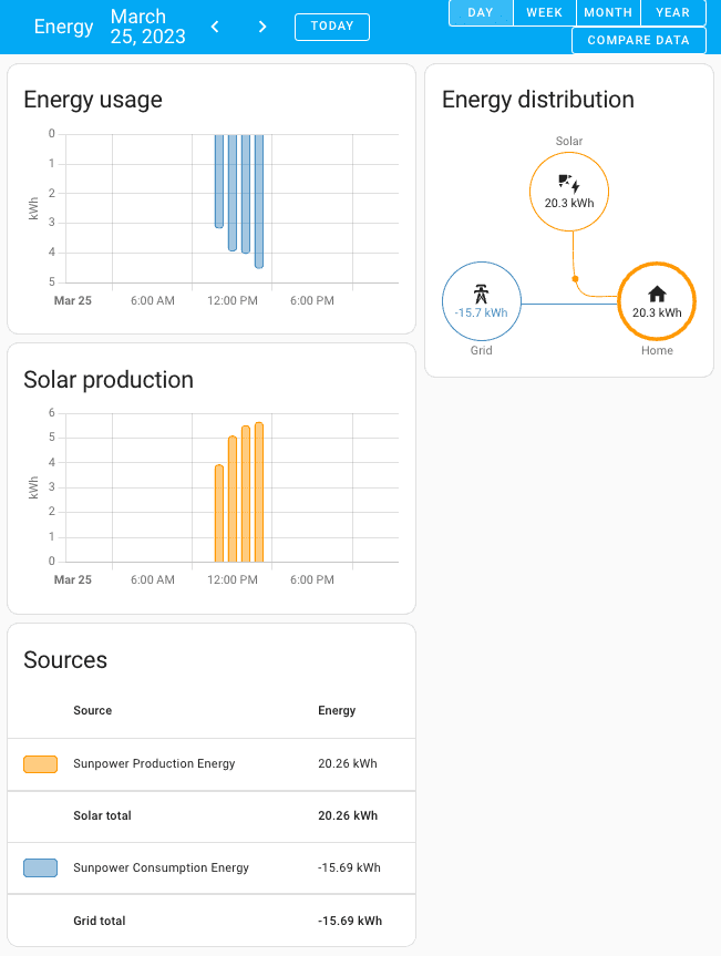
The Energy dashboard in Home Assistant
Now that I have this working I will probably realize that the hass-sunpower using HACS is a way better solution, but only the RESTful integration would need to change, all of the network and proxy configuration would carry over.
Finally, if you’ve made it this far, you probably realize that it would be way better if SunPower offered a reasonable API for home integrations, instead of making people take these ridiculous steps… please let your SunPower contact know!
What’s your SunPower and Home Assistant experience? If you’re following in my footsteps (yikes), how did it go?… please leave a comment, below!
Update November, 2025: see my most recent post on self-hosting PV6, which has my latest recommendations following the SunPower bankruptcy.
Well, if you landed on this post you either have a need to cure your insomnia or you have a very specific problem. I recently decided to become a sun farmer, and went with SunPower, which is great, but they don’t offer integrations beyond their decent but limited web and mobile apps. In particular, I wanted to integrate with Home Assistant, because… well, just because.
The main solar interface from SunPower is the PVS6 (successor to the PVS5), and by connecting to an administrative interface it is possible to pull some detailed data like specific energy output and health for each panel. The good news is the PVS6 comes with two ethernet ports, one for a WAN to connect to their servers and one for a LAN that will allow access to the administrative UI, and all one needs to do is connect to said port and then… hey, WTF? My PVS6 doesn’t have either of these ethernet ports! So, yeah… evidently there is a new version of the PVS6 that does not have ethernet ports, and the primary WAN connection is via wifi.
A blurry photo of the ethernet-port-less SPV6
After digging around teh webz, it seems that the PVS6 USB ports will work with a USB to ethernet adapter, but several people reported some adapters didn’t work. Unsure if the magical solution is the adapter needs to be USB 2.0, but I found a $7 adapter on Amazon, and it just worked. I connected my laptop to the USB2/LAN port, the PVS6 assigned an address to my laptop, and browsing to http://sunpowerconsole.com/ provided a web administration interface. However, PVS6 is not within convenient ethernet wiring distance, so I dug around some more and found Dolf Starreveld’s page, which included an amazingly comprehensive doc, Monitoring a solar installation by tapping into a SunPower PVS5 or PVS6. This doc starts with the assumption you have a PSV* with an ethernet connection and want to get to wifi, and with my USB to ethernet dongle, that’s what I had, so all I needed to do was mount a Raspberry Pi in the PSV6 to act as a router / bridge to my network. But while reading his doc, I noticed a mention of a hotspot interface available for a limited time after PVS6 power-up, and a link to a SunPower doc on commissioning the PVS6 via wifi… this sounded promising.
Sure enough when I scanned for wifi connections, I found a SunPower SSID that matched my system. And since my system had been on for days, it didn’t appear that the 4-hour window applied, so great news! The formula for the SSID is “SunPower” immediately followed by characters five and six of the PVS6 serial number; immediately followed by the last three digits. The password follows a similar formula, characters three through six of the PVS6 serial number; immediately followed by the last four digits. Once connected, I had the exact same access I had when directly connected via ethernet.
But the cool stuff isn’t really in the web UI, you need to call it directly. For example:
Will show all devices and panels, with a ton of data on each. Dolf Starreveld’s document has a ton of details.
Since I don’t plan to run this from my laptop, I still need to bridge the network… several people have written about using a dedicated device like a Raspberry Pi, including Scott Gruby’s Monitoring a SunPower Solar System, where he uses a very lightweight Raspberry Pi Zero W, and then a simple haproxy setup. However, I’d like to avoid another device (especially with the current price for Raspberry devices – holy crap), and my Raspberry Pi 4 file server connects via ethernet, so I’ll likely use its wifi to connect to the PSV6 and run the proxy from there. After that I’ll configure Home Assistant and likely bore you with another posting.
And, no sooner do I get to the end of writing a post when I realize that the wifi network has vanished, so I either need to find a way around that problem or else I’m adding a router to my PSV6.
Are you doing anything interesting and hacky with your SunPower system? Do you have cool integrations with Home Assistant? Did you stay awake through this whole post?… please leave a comment, below!
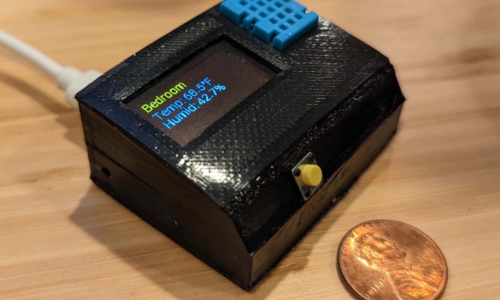
For the 3 people that have been reading my posts, you know my journey from ESP8266 hacking off the shelf smart switches to creating custom devices, most of which I connect to Home Assistant so that smart devices are secure and don’t rely on the existence of any particular vendor. The next step in this journey is using ESPHome to simplify creation of custom software for ESP8266/ESP32. For my first project I created ESPHome Temperature and Humidity with OLED Display.
Why ESPHome?
Why use ESPHome instead of something like Arduino Studio? Simply put, its simple but powerful. As an example, I made custom software for a temperature & humidity reader for my bathroom that was 8 custom lines of code (which wasn’t really code, but configuration). YAML configuration files provide access to a ton of sensors, and if you need to dig in deeper with more complicated functionality, ESPHome provides Lambdas that allow you to break into custom C++ at any time.
One of the other cool things about ESPHome is, while it integrates seamlessly with Home Assistant, the devices are meant to run independently, so if a device is out of range or has no network connection, it still performs its functions.
And I wanted to learn something new, so…
Why This Sensor?
I have a few temperature sensors around the house and I also keep one in the camper van, mostly out of curiosity so I can compare it with the in-house temperatures using graphs on Home Assistant. However, I realized that when I went camping I wanted access to the temperature, but couldn’t do so without being connected at home. The old version of the van thermometer was based on an ESP8266 Garage Door opener (I never shared that posting, so sorry, or you’re welcome) and I didn’t want to update it with a display screen, as I really don’t need that for a garage door (yes, I realize something not being needed usually doesn’t stop me from building it). I decided that I might as well take the opportunity to use ESPHome since it was simple and worked offline.
It’s Time to Build
I won’t go into the details of setting up Home Assistant, but if you are into home automation at all, it is super awesome. Installing the ESPHome add-on gives enables the flashing and managing of ESP8266/ESP32 boards, and they automatically connect to Home Assistant at that point.
For the lazy, ESPHome is generally a few clicks and a little copy pasta. For this project, it’s no different, with the step-by-step details available on my Github project page.
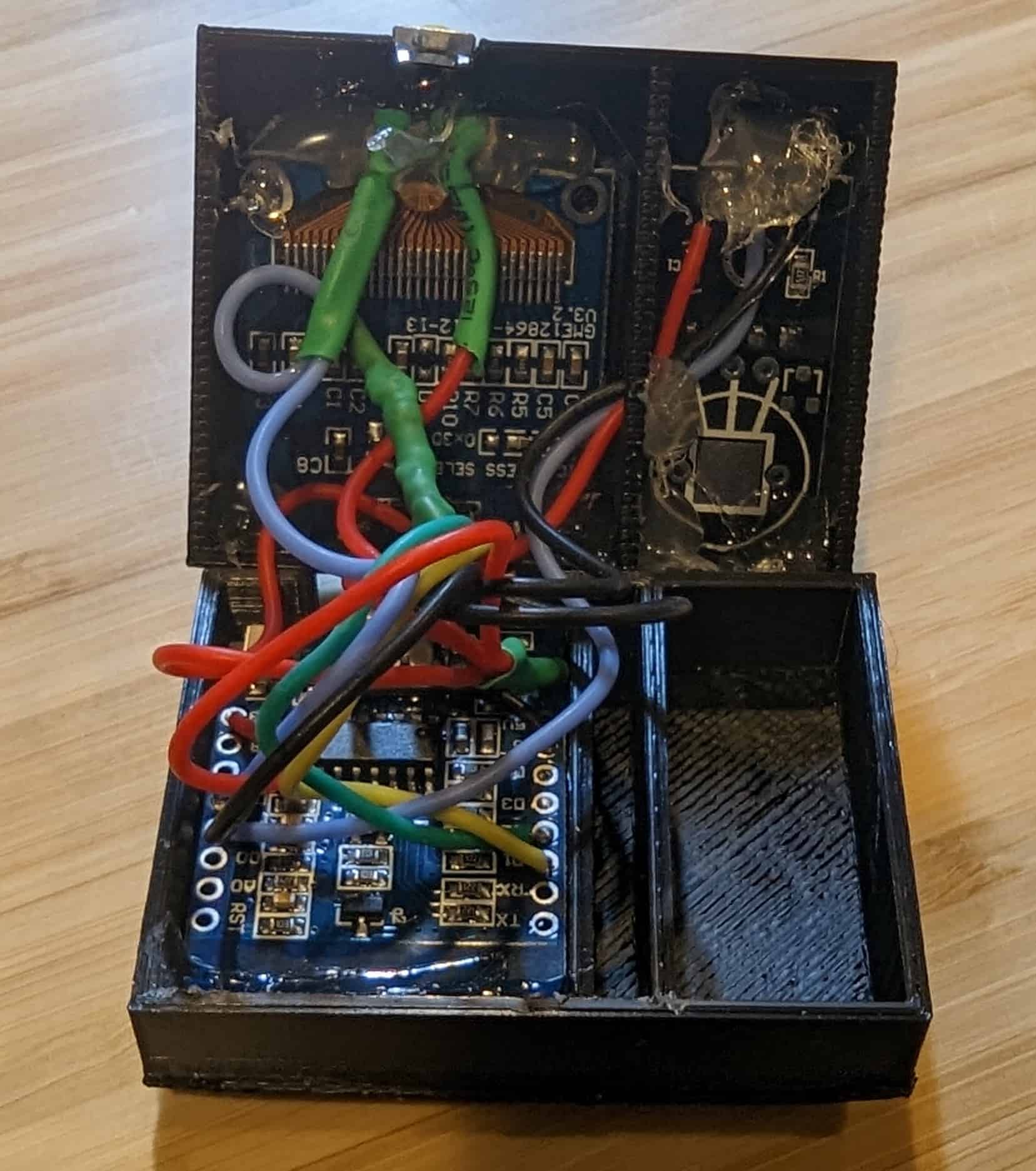
Wiring complete on DHT11 and ESP8266 (ESP-12F) before gluing case together
For the hardware, I used the very tiny ESP-12F, DHT11 sensors, this OLED display, and a few miscellaneous components. All of these fit pretty nicely in the case, although it is a pretty snug fit, so I highly recommend a very thin wire, and this 30 Gauge silicone wire was super great for the job. Exact components, wiring diagram, and the STL files to 3D print the case are on my Github project page.
When assembling, removing the pins from the DHT11 board and soldering the wires directly to the board will allow it to be flush against the case, giving better exposure to the sensor and fitting better. The DHT11 is also separated from the ESP8266 board as I was hoping to create some insulation from any heat from the board impacting the temperature reading (not sure that work). There is a hole between the chambers to thread the wires, and I suggest a bit of hot glue to block air flow once wired.
As you can see in the photo, I used generous dollops of hot glue to hold the components in place… it isn’t pretty, but nobody will ever see it (well, unless you photograph it and blog about it, in which case still, probably nobody will see it). I sealed the case with Zap-A-Gap glue, as I found original Super Glue was way less effective.
Instructions
Plug it in.
Okay, well… it’s a little more than that. The screen will alternate between showing the temperature and humidity in text format and a 24 hour graph that is a bit useless for now since I am not sure how to get the historical values to label the graph. The button will toggle screen saver mode on / off, and the screen saver activates automatically after a short amount of time.
If you want to get a little fancier, I have this sensor in the bathroom and it will turn the vent fan on (via Home Assistant) when the humidity reaches a certain level… it’s useful for anything where you want to control devices based on temperature or humidity, and even more useful if someone might want to see the temperature.
Are you doing home automation with ESPHome? Do you have suggestions or requests? Did you actually read this blog post for some reason? I want to know… please leave a comment, below!
When it was clear that nobody was asking for or needed my BART Train Monitor with ESP8266 and SSD1306 display, I knew the obvious response was to invest more time into the project by creating a model for a 3D printed case.
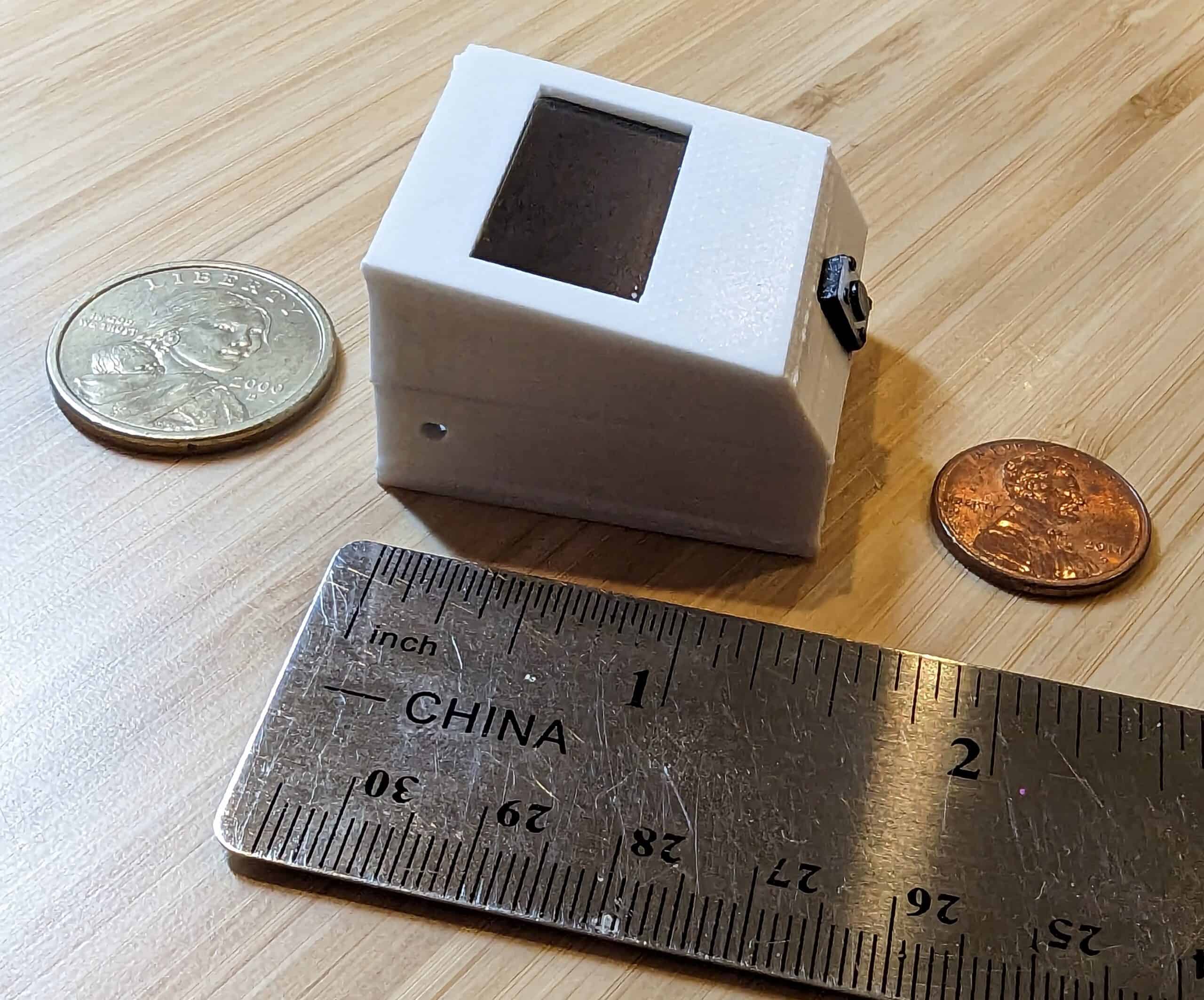
The BART watcher 3D printed case
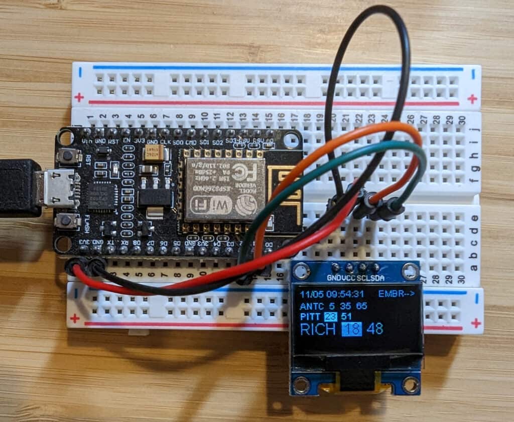
I made a few hardware adjustments from the original build, and I am using the much smaller NodeMcu ESP-12F for the board, and this SSD1306 0.96 Inch OLED I2C Display Module, which features a full text row in yellow and the rest of the screen in blue. Finally, I added a button to the project, because everything needs a button (I happened to use these).
The case isn’t fancy, but it works… the final build is approximately 1.25″ x 1.5″ x 1″ (width x depth x height), or 3.5cm x 4cm x 2.25cm for most of the planet. One challenge with the size is everything is extremely tight in the case, so I recommend using very thin wire in your build. There are two 3D models, the base and the cover, assembly is just cramming everything in and gluing the case together. I was using relatively thick wires and everything is so compressed I didn’t even need to glue the boards in place, but it would probably be a good idea to use a little hot glue to secure things inside.
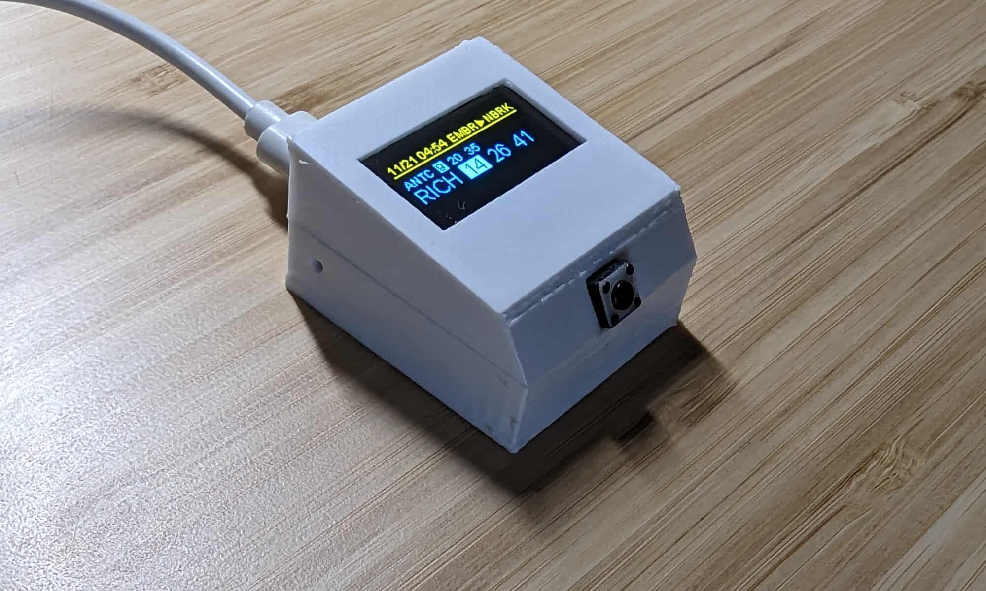
The blue and yellow OLED display with BART schedule
I really like the two color display, which was more of an accident than anything as one of the original all blue displays seemed to go bad and was very dim, so I ordered replacements.
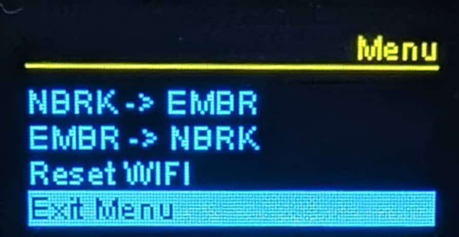
With the addition of the button, I was able to add some new functionality. A quick press of the button will toggle the screen off and pause network updates, effectively a screen saver sleep mode. Another quick press turns the screen back on. A long press will enter menu mode. While in menu mode, a short press will iterate through the menu items, and a long press will select the menu item.
OLED display with BART Watcher menu
All of the source code, 3D models, and wiring instructions can be found on my Github page bdurrett/BART-watcher-ESP8266. The project still needs work to be generic enough to be useful to anyone, but since this works for me (and I don’t think anyone else actually needs this), I will likely stop further development. That said, if anyone wants to contribute, I’d be happy to collaborate with anyone!
I frequently commute on BART and wanted a convenient way to tell when I should start walking to the train station, ideally something that is always accessible at a glance. A gloomy Saturday morning provided some time to hack together something…
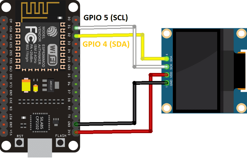
ESP8266 to SSD1306 wiring diagram
I had already purchased a ~1 inch SSD1306 display and had extra ESP8266 boards laying around, so I figured I would start there. Wiring the screen to the board is super simple, just 4 wires (see diagram).
From there is was pretty simple to pull the train real-time data using BART Legacy API. BART also offers modern GTFS Schedules, which is the preferred way to access the data, but from what I could tell, this would make the project significantly more difficult given some of the limitations of the ESP8266. So, I went the lazy route.
Coding was pretty simple, most of the time was spent rearranging the elements on the screen. Well, actually most of the time was spent switching from the original JSON and display libraries I chose as I wasn’t happy with them.
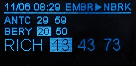
BART-watcher-ESP8266 (early layout)
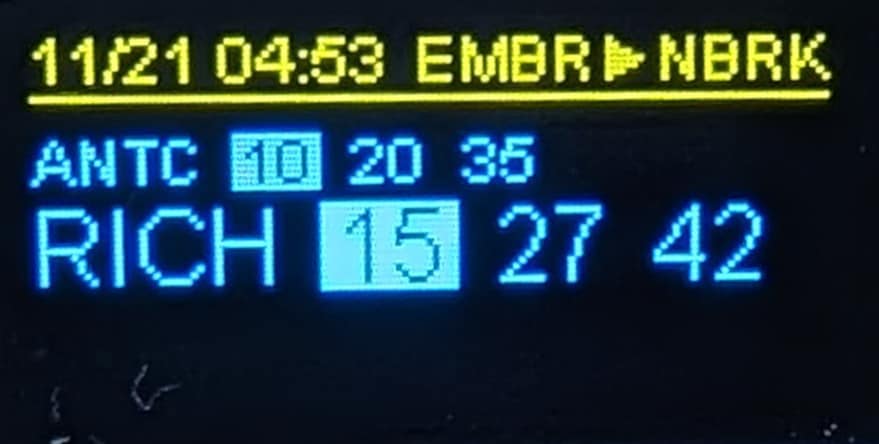
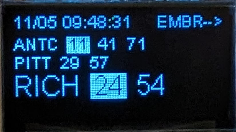
There’s a lot to fit into a 1-inch display, but I got what I needed. The top line shows the date / time the station information was collected, and the departing station. The following lines are trains that are usable for the destination station, with the preferred (direct) lines in large type, and less-preferred (transfer needed) in small type. Finally, if a train is within the sweet spot where it isn’t departing too soon to make it to the station but I also won’t be waiting at the station too long, the departure time is highlighted. Numbers are minutes until departure, “L” means leaving now, and “X” means the trains was cancelled (somewhat frequent these days).
In the example above, these are trains leaving Embarcadero for the North Berkeley station (not shown), Antioch and Pittsburg/Bay Point lines require a transfer, Richmond line is direct.
At some point I would like to use a smaller version of the ESP8266 board and 3D print a case to make it a little nicer sitting on a desk, but then again, there’s almost zero chance I’ll get around to it. If anyone is into 3D printing design and wants to contribute, I’ll give you all of the parts needed.
The code / project details are available on my GitHub page at BART-watcher-ESP8266, feel free to snoop, contribute, or steal whatever is useful to you.
The full build of BART Watcher on ESP8266 and SSD1306 OLED display
Do you have suggestions for features you think would be cool, want to remind me that I waste a lot of time, or maybe you even want one of these things? Please leave a comment, below!
If you followed my previous posts on hacking IoT (Internet of Thing) devices to make a more secure and sustainable smart home, you may have the perception that this is an overly complicated process that no sane person would pursue. You’re not wrong, and over the last year I’ve had several failed attempts at hacking devices for various reasons from the casing requiring a saw to the programming pins being inaccessible. However, I discovered CloudFree, love their products, and think they provide a simple solution for making a smart home that is truly under your control.
Note: This is not a paid posting, I am receiving no compensation, goods, or services in exchange, and have no ownership interest in CloudFree – I am simply a happy customer.
As a quick reminder, most IoT devices require an external Internet connection to function. The problem with this is it is less secure, as a random company, often in another country (frequently China) is controlling and updating the software, as well as harvesting data. Also, if the company goes out of business, this often means your device ceases to function.
I stumbled upon CloudFree as I was looking for an alternative for the Amazon Smart Plug, which is great, but could only be controlled by Alexa, and I wanted something that could also be controlled by Google Nest, Home Assistant, a web interface, or pretty much anything. As implied by their name, CloudFree sells devices that do not require an Internet connection, emphasizing user ownership and control. This sounded perfect.
Dipping my Toes in: the CloudFree Smart Plug
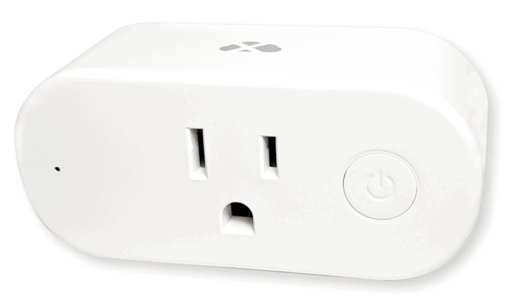
CloudFree Smart Plug 2
In addition to selling third-party devices, CloudFree was manufacturing their own Smart Plug, which had a similar form factor and came pre-installed with Tasmota, an open source UI. And, at $13 it was a good deal. I ordered two and about a week later they arrived.
Setup was super simple… plug it in, connect to the temporary wifi it creates and configure it to connect to your home wifi. You can also setup passwords and things like MQTT. It took about 3 minutes and the switch had both a web interface and was fully connected to Home Assistant, making it accessible by Alexa as well.
The other details were nice, too… the packaging is simple paper and thin cardboard, and the actual device looks good and seems to have quality consistent with nicer devices I’ve seen. Oh, and it has a lot of functionality for things like tracking power consumption. I ended up ordering three more, which took a few weeks to arrive due to them being backordered.
Even Deeper: CloudFree Smart Bulb
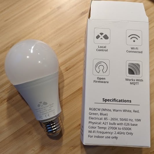
CloudFree Smart Bulb
I needed EVEN MOAR switches, and I decided to try the one other product CloudFree makes, their CloudFree Smart Bulb. This is a pretty basic 10W LED bulb that also allows you to control the color, coolness, and brightness, again with the super easy setup and Tasmota UI. I’ve just started playing with it, so I can’t give much of a review, but it seems well-made and does exactly what I was expecting. It reads “indoor use only”, but I am tempted to try it in my enclosed light post and change the color for holidays, events, or maybe an alarm. This shipment was relatively quick, switches and bulbs arriving in about a week, and $15 for the bulb seemed like a good price.
CloudFree Wish List
I am really happy with CloudFree overall – it is a great resource for finding user controlled smart home devices. They have a bunch of third-party sensors, plugs, and gadgets that all are user controlled, no Internet needed. If I could change anything, it would simply be adding more products, ideally made by CloudFree. Specifically, I would love to find a well made light switch (ideally with a dimmer), or the holy grail, a 3-way dimming light switch. But, for what they have right now, they are great and I recommend them for anyone looking for a simple way to add to their smart home.
Have you found other great sources of secure, sustainable IoT devices? I’d love to know about them – please leave a comment below!
Using TUYA-CONVERT is preferred since it doesn’t require opening up a device or soldering, but it seems like all newer devices are using software that can’t be hacked wirelessly anymore, so you will likely need to open your smart home device. Now, let’s go void some warranties!
Gosund Smart Dimmer Switch (SW2)
This dimmer switch has a nice capacitive touch panel for changing the lighting level, so it feels a lot like adjusting something on a touch screen. Since Gosund also makes the SW1 switch I started with, I was hopeful it would be similar and I could avoid soldering… not so much.
Gosund Smart Dimmer Switch (SW2), wires soldered to the circuitboard to enable a serial connection.
Like the SW1, the SW2 requires a Torx T5 screwdriver to open it. Unlike the SW1, the SW2 dimmer switch has two circuitboards in it, connected by a small cable. Reading about this switch, one person claimed it could not be hacked with that cable connected – this is not true, and I bricked one of these detaching the cable… not recommended. Unfortunately, the serial connections are in the middle of the board, so the process I used with test hook clips would not work like they did on the SW1. However, the connection points are pretty big and well-labeled, so soldering wires to them is pretty easy. Once I had connections, the process was super simple to install new software, exactly like the SW1. It’s nice when things just work!
But, of course, things didn’t just work. When I installed the dimmer the dimming functionality didn’t work from the switch. Looking at the Tasmota template details for the Gosund SW2 Dimmer, this switch requires extra scripting to function properly. However, scripting is not available in the basic Tasmota software, so it needed a different version. Fortunately, once you have Tasmota installed, switching the software is easy and only requires a web browser, selecting “Firmware Upgrade” from the web interface. Unless it isn’t so easy. Trying to install tasmota-scripting.bin from the unofficial releases failed, and first required installing the tasmota-minimal.bin to get the smallest install and then installing the compressed version of the unofficial release, tasmota-scripting.bin.gz (only the .gz version would install successfully). I used the OTA (over the air) install for the minimal software (pointed to the official OTA releases), and manually uploaded the scripting gzipped binary downloaded from unofficial experimental builds. Once installed, there are new menu options in the web interface, “Configuration” -> “Edit Script”, and simply paste and enable the script from the template page. None of this was complicated, but is also wasn’t very obvious… hopefully I can save you some trial and error.
And, the switch works great and immediately worked with Alexa (make sure emulation is set to “Hue Bridge” to enable Alexa to use the dimming functionality.
Youngzuth 2-in-1 Switch
Youngzuth 2-in-1 Switch with wires soldered to make a serial connection to the TYWE3S.
The Youngzuth 2-in-1 Switch is actually two switches that fit into the space of a single switch. When I opened the switch (Phillips head screwdriver) and started looking around the circuitboard, I couldn’t find any connection points for the serial interface. I finally hit the point I had been dreading… needing to solder directly to the chip.
The Youngzuth 2-in-1 uses a TYWE3S package and fortunately a lot of details are available on the Tuya Developer website, so it was pretty easy to figure our the chip connections. I really hate soldering, especially on tiny components next to other tiny components, so I had a margarita to steady my hand.
TYWE3S pin connections, colors showing all pins needed to reprogram
Once wires were connected, installing the software was a breeze. Configuration was also easy, with an example provided in the Youngzuth 2-in-1 template.
Full disclosure, I have not yet installed the Youngzuth switch, as I made a rookie mistake, not realizing there is no same-feed neutral connection at the switch location. Once installed I will post an update if anything required extra work.
If you have any questions or different experiences with these devices, please leave a reply below!